System Introduction
Overview
This section gives you a brief introduction of the hardware and software of the NcStudio Phoenix Three-axis Engraving System.
Hardware
Industrial computer: NC60A, NC65C, NC68A, etc.
Lambda controller
- Lambda 21B: Applicable to bus control systems
- Lambda 21A: Applicable to non-bus control systems
- Lambda 20A and so on
EX series terminal board: EX31A
For the hardware connection diagram, see Hardware Connection Diagram.
Software
For introduction of the NcStudio Phoenix Three-axis Engraving System software interface, see Software Interface.
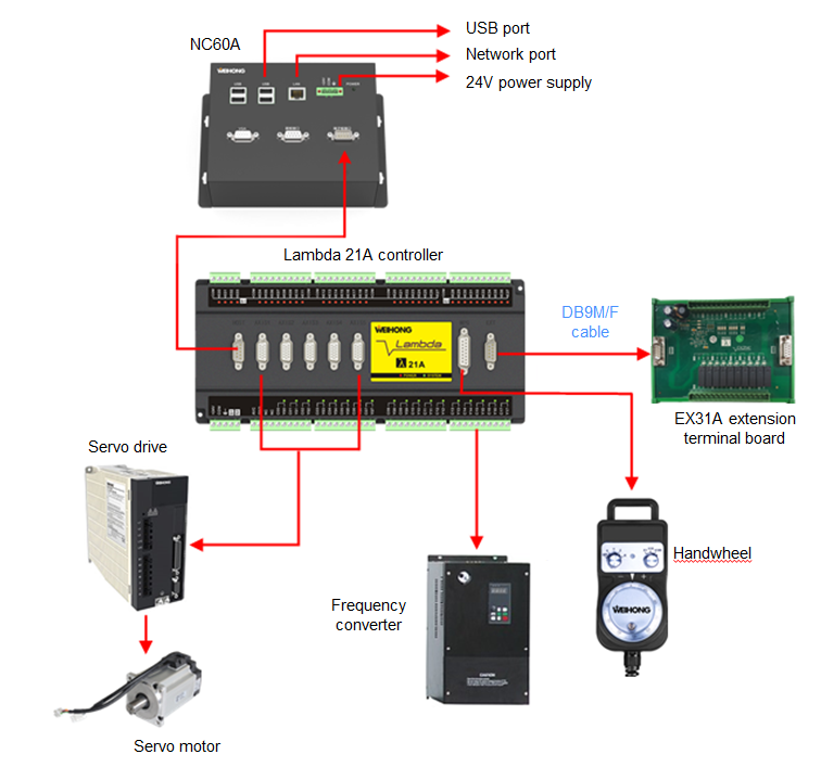
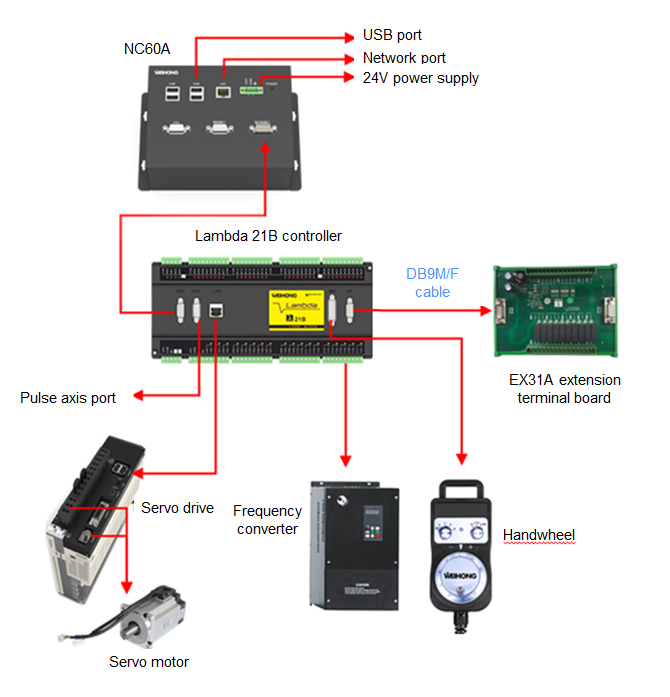
Hardware Connection Diagram
Hardware connection method varies based on the control system type. Example of a non-bus control system and a bus control system using NC60A are shown below.
Non-bus control system
Bus control system
Software Interface
This section gives you a brief introduction of the software interface of the NcStudio Phoenix Three-axis Engraving System.
NcConfig
The homepage of NcConfig is shown below:
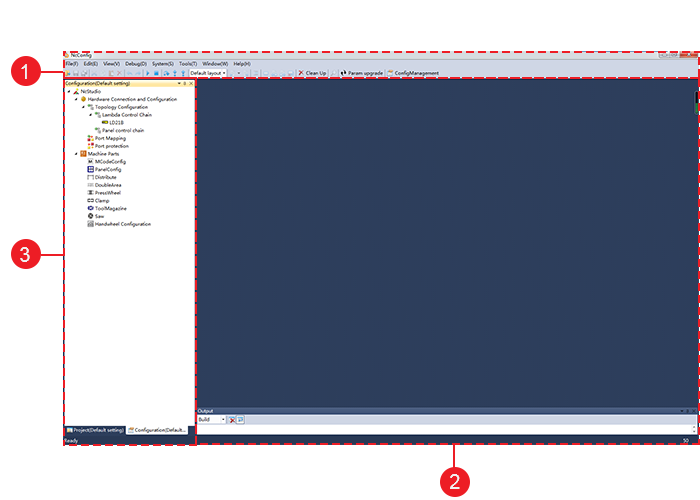
Menu bar
Function area
Project configuration area
Function Area
Target functions are selected in the project configuration area and debugged in the function area.
Project Configuration Area
Click the Project or Configuration tab in the project configuration area's lower part to use different functions (If the Project tab is not displayed in this area, go to View > Project in the menu bar).
Functions on the Configuration page:
- Topology configuration
- Machine parts
- Port mapping
- Port protection
NcTune
The homepage of NcTune is shown below:
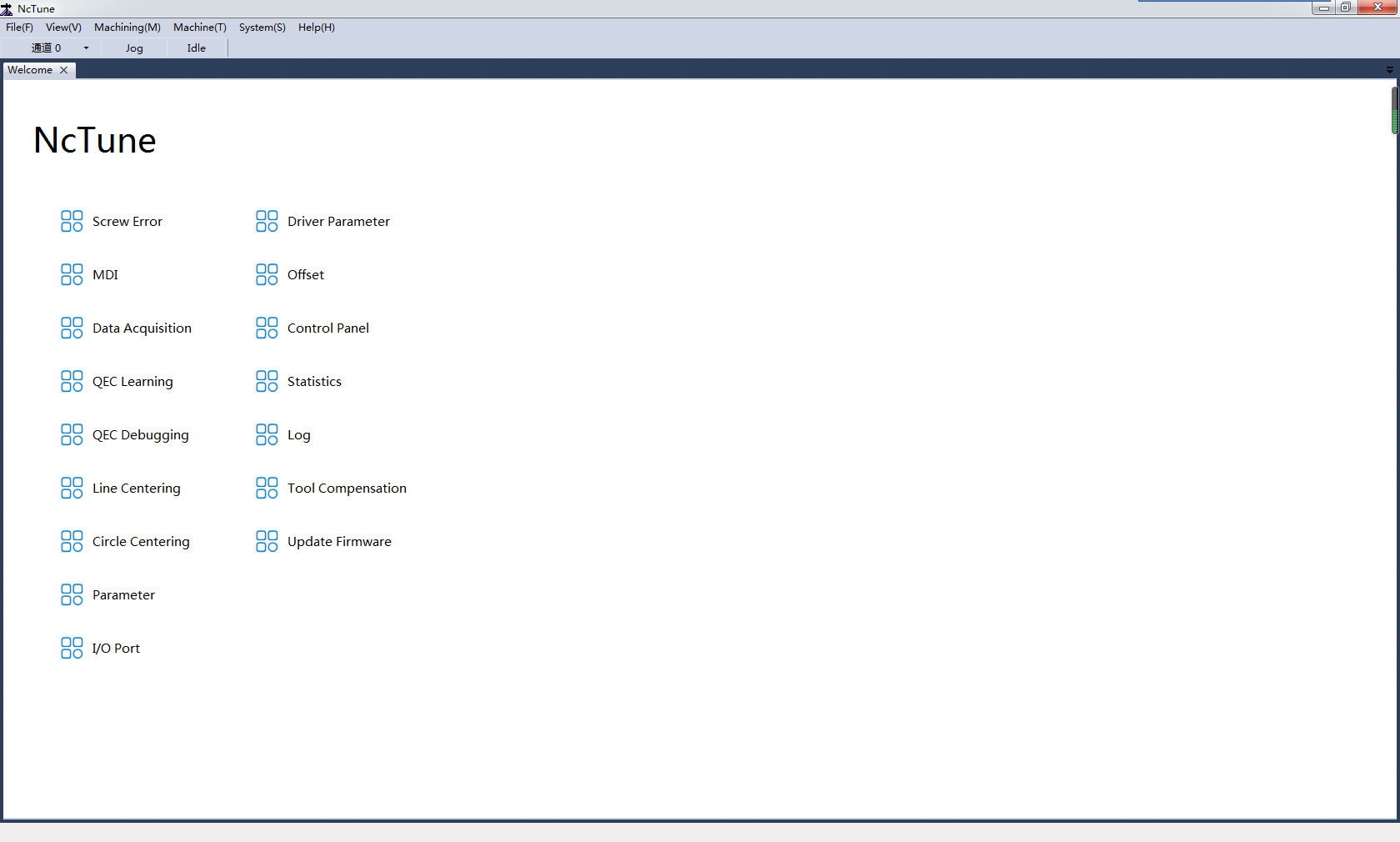
Menu bar
Status bar
Welcome page
NcStudio
The homepage of NcStudio is shown below:

- Menu bar
- Status bar
- Axis coordinate area
- Override setting area
- Machining information area
- Function window
- Operation mode area
- Operation button bar
Menu Bar
You can access the following functions in the menu bar:
File: Open and Load, Load History File, Unload, Generate Installation Package, Multi-Config Pack Up, Restart software, Close System, Restart System, Show Desktop, and Exit
Program: Machining Wizard, Machining Information, and Machining Statistics
Machine: Single Block Execution, HW Guide, Current Point as Work Zero, Cycle Start, Cycle Pause, Cycle Stop, Simulate, Resume, Jiggle, Homing, To Work Zero, To Fixed Point, Centering, MDI, Datum Setting, Adjustment, Datum Cancel, Double Y Jiggle, Double Y Origin Detection, Clear Servo Alarm, Reconnect Drive, and Reconnect Controller
Advanced: Selective Machining, ENG choose tool and row, AdvAuto, Cycle Setting, Timed Stop, and Nearby Resume
System: Log, Global Parameters, Driver Parameters, Tool Compensation Parameters, Tool Offset, Change Password, Language, Multi-Z Mode Switching, Data Backup, NcTune, Remote Assistance, NcCloud, M Instruction Table, and About
Status Bar
You can access the following functions in the status bar:
System modes: Auto, Manual, and Homing
System status: Idle, running, paused, or emergency stop.
Information/alarms: Current information and alarms
Double-click the blank area to open the Log dialog box to view system alarms, errors and information.
Axis Coordinate Area
The axis coordinate area is shown below:
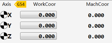
It shows the name of the current workpiece coordinate system, and the mechanical and workpiece coordinates of the axes.
After an axis has gone to the machine origin, the  icon will be displayed before the axis in this area.
Override Setting Area
The override setting area is shown below:
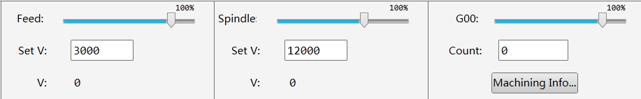
In this area, you can set the spindle rotational speed, feed rate and G00 speed parameters by entering values in the corresponding field.
You can adjust the spindle rotational speed, feed rate and G00 override/multiplier by dragging the corresponding slider.
Actual spindle rotational speed = Spindle rotational speed multiplier * Spindle rotational speed setting

Actual machining speed = Feed rate multiplier * Feed rate setting

Actual G00 speed = G00 multiplier * G00 setting
Machining Information Area
The machining information area is shown below:

It shows the current machining progress, current program line number, machining duration and current tool number.
Function Window
Click the following tabs in the function window to access different functions:
Track: Displays the machining or dry running track.
Offset: Setting of the workpiece offset and public offset, Z-axis lowing and lifting
Calibration: Setting of the tool sensor position and tool calibration method (Auto Measure, Z Mobile Cali, Z Manual Set)
Program Management: Loading, editing, deleting, renaming and creating programs
Common: Viewing and setting of common parameters
Log: Viewing of information, alarm, and error logs.
Port: Viewing of port status and polarity, testing of ports, modification of port polarity, and setting of the filter
Operation Mode Area
The system supports the following operation modes:
Auto
The loaded program is displayed in this mode.
Common function: Going to the fixed point
Common ports: Spindle, Cool, Vacuum, and Lube. The common ports can be modified in NcConfig.
Manual
Axis buttons: control of the axis movement in each direction
Jog
Click and hold an axis button to make the target axis move in the target direction continuously at the relatively lower speed.
Click and hold multiple axis buttons at the same time to make the target axes move in the target directions continuously at the relatively lower speed.
Mainly used to move the X axis and Y axis at the same time.
Click and hold an axis button and the Rapid button at the same time to make the target axis move in the target direction continuously at the relatively higher speed.
Click and hold multiple axis buttons and the Rapid button at the same time to make the target axes move in the target directions continuously at the relatively higher speed.
HW: In this mode, you use the handwheel to control the machine movement. Select the axis direction and multiplier on the handwheel and turn the handwheel knob by a certain degree to make the target axis move in the target direction.
Stepping: Select 0.01, 0.05, 0.1, 0.5, 1, 5, or 10 (the unit is mm), or enter a value in the blank field. Click and release an axis button to make the target axis move in the target position by the set step.
Note: Please do not set the step to a value that's too large to avoid damage due to misoperation, and do not click an axis button too frequently in short time.
Common function: Going to the fixed point
Common ports: Spindle, Cool, Vacuum, Lube, etc. The common ports can be modified in NcConfig.
Homing
Tick Execute homing when software starts to make the axes go to the mechanical origin upon software start.
You can also check and clear the homing average values in this area.
Operation Button Bar
You can use the following functions with buttons in the operation button bar:
In Auto and Manual modes:
Loading and unloading of programs
Axis clearing
MDI, selective machining, going to the workpiece origin, and simulation
Using the handwheel to control machining movement
Starting, pausing, or stopping machining; resuming machining from the interrupted point
In Homing mode:
Making the axes go to the mechanical origin
Starting, pausing, or stopping machining; resuming machining from the interrupted point