Commissioning
This section mainly introduces operations to quickly do commissioning for Double-tool CNC System.
The process for commissioning is as follows:
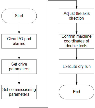
If there is no special instruction, please execute the above operations in Technician page (Manufacturer permission is required).
Clear I/O Port Alarms
It is used to clear I/O port alarms, including E-stop alarm, limit alarms and drive alarms, so as to establish good communication between the system and the servo drive.
Clear E-stop Alarm
To clear E-stop alarm, check E-stop button:
If it is pressed, release the button.
If it is not pressed, modify the polarity of port E-stop.
See Execute I/O Port Related Operations for details.
Clear Limit Alarms
When the machine tool triggers the limit switch, the system will send a positive/negative limit alarm.
To clear limit alarms, move the machine tool towards the opposite direction of the limit switch.
Clear the Drive Alarms
To clear the drive alarms, do the following:
Check if the wiring of the drive is connected correctly and securely:
- If it is, proceed to the next step.
- If it is not, correct and tighten the wiring.
Check if the setting value of parameter Drive Station Address is the same as the drive station address of the machine tool:
- If it is, proceed to the next step.
- If it is not, modify the setting value of the parameter according to the drive station address of the machine tool.
Optional: If the system is under the bus configuration, to clear the common drive alarms and improve commissioning efficiency, in the menu area, click Machine → Clear Drive Alarm.
Set Drive Parameters
This operation is used to set drive parameters via the software after the system is well connected to the servo drive.
Before setting drive parameters, make sure the system has been connected to the hardware correctly.
To set drive parameters, do the following:
In the menu area, click System → Drive Parameters. Drive Parameters dialog box pops up:
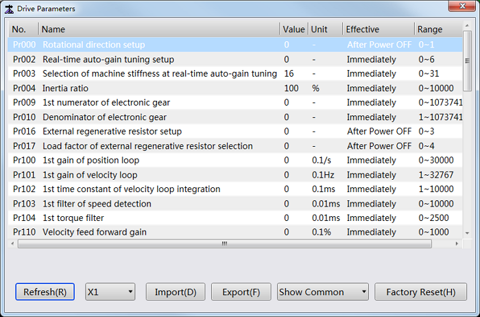
Select the target axis.
Double click the target parameter, and enter a value.
In Drive Parameters dialog box, you can also do the following:
- To refresh values of drive parameters, click Refresh.
- To import drive parameters that have been set before, click Import and select a file.
- To export drive parameters, click Export and select a path.
- To show common/all drive parameters, select Show Common / Show All.
- To initialize drive parameters, click Factory Reset.
Set Commissioning Parameters
This operation is used to set parameters for commissioning in the bus control system.
To set commissioning parameters, do the following:
In the menu area, click System → Parameters. Parameter dialog box pops up:
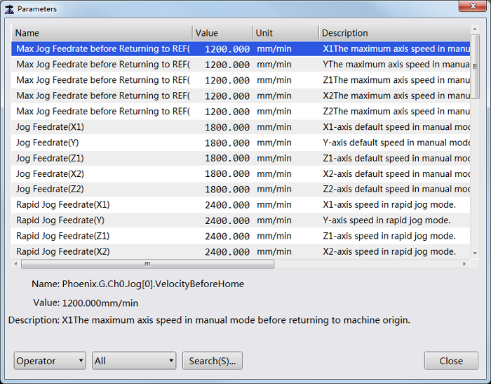
Select Manufacturer permission in the lower left, search and set the following parameters:
Screw Pitch: the axial distance between the corresponding points of two adjacent teeth on the threads.
Its setting should match the actual condition.
Mechanical Reducer Ratio: the ratio of reducer input speed to output speed.
It consists of parameter Numerator of Mechanical Reducer Ratio and parameter Denominator of Mechanical Reducer Ratio. And its setting should match the actual situation:
Mechanical Reducer Ratio
= Reducer Input Speed / Reducer Output Speed
= Teeth No. of Drive Wheel / Teeth No. of Driving Wheel
= Motor Rotational Speed / Screw Rotational Speed
Encoder Digit: its setting should match the actual situation.
Electronic Gear Ratio: the ratio that the servo enlarges or shrinks the received pulse frequency. If it is greater than 1, the servo enlarges the received pulse frequency; if it is less than 1, the servo shrinks the received pulse frequency. It is set to 1:1 by default.
It consists of parameter Numerator of Electronic Gear Ratio and parameter Denominator of Electronic Gear Ratio. And its setting should match the actual situation.
Adjust the Axis Direction
This operation is used to check if the positive direction of each axis is the same with the direction stipulated by Right Hand Rule, so as to avoid damage to the machine tool due to incorrect direction.
Taking X-axis as an example, to adjust the axis direction, do the following:
In the menu area, click System → Parameters. Parameter dialog box pops up:
Select Manufacturer permission in the lower left, search parameter Axis Direction (X), and check its setting value.
Judge the positive direction of X-axis according to the Right Hand Rule.
In Manual mode, click X+ or X- button to move X-axis and observe its moving direction.
Optional: If the actual moving direction is opposite to the judged direction, change the setting value of parameter Axis Direction (X) to the opposite value.
Confirm Machine Coordinates of Double Tools
This operation is used to execute returning to the machine origin, confirm the distance between double tools, and set datum when you use the system at the first time, so as to adjust coordinates before machining.
There is no need to set a returning order for all axes during setting datum, and set datum again after recovering from alarms, like power interruption and E-stop, because the system will automatically read datum information.
The double tools share the same machine coordinate system.
To confirm the machine coordinates of double tools, do the following:
Switch to REF mode in the mode control area.
To execute returning to the machine origin, click one of the following operational buttons:
Click All Axes. The system returns to the machine origin in the order of Z1-axis, Z2-axis, X-axis, and Y-axis.
Click X Back Home / Y Back Home / Z1 Back Home / Z2 Back Home. The specified axis returns to the machine origin.
For safety, it is suggested to firstly return Z1-axis and Z2-axis.
Alternatively, in the menu area, click Machine → Return to Machine Origin and execute returning to the machine origin in Return to Machine Origin dialog box:
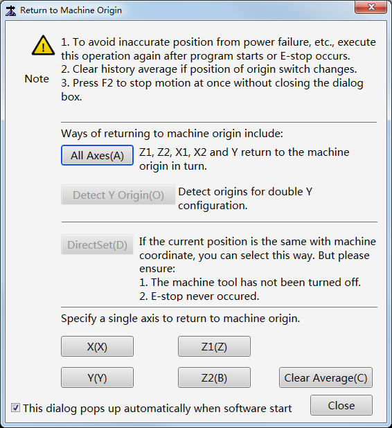
If This dialog pops up automatically when software starts is checked, the dialog box will pop up automatically when software starts.
Measure the distance between tools of X1-axis and X2-axis, and set the measured value as the value of parameter Home Position(X2).
Note: Parameter Home Position(X1) and parameter Home Position(X2) should be modified synchronously to confirm that the difference between machine origin of X1-axis and X2-axis keeps the measured value.
To set datum for the axis that has returned to the machine origin, do one of the following:
- In the menu area, click Machine → Datum Setting, and select the target axis.
- In the mode control area, click Set button after the target axis.
After setting datum, the sign
 appears before the related axis.
Execute Dry Run
This operation is used to know the running area and the speed steadiness of the machine tool before machining.
During executing dry run, the machine tool moves like normal machining without turning on/off valves.
To execute dry run, in the mode control area, switch to Auto / Manual mode, and click Dry Run.