Object Operations
This section introduces the drawing tools that are used to draw objects in the function window for machining and operations for better effects of object editing.
If there is no special instruction, please execute object operations in Operator page.
Object Drawing
The drawing tools include the following:
 : dot
: dot : polyline
 : line
 : elliptic arc
 : arc
: arc : ellipse
 : circle
 : polygon
 : star
 : rectangle
 : text
 : gallery
After drawing, do the following:
To exit drawing, right click or press Esc.
To adjust the object, select the target object and do one of the following:
To modify the size and position of the object, directly input the values.
To modify the size of the object, drag the rectangular points around the object.
Draw a Polyline
A polyline is a chain of lines and arcs that are joined together into one object. It includes line and tangent arc. The tangent arc corresponds to the arc.
To draw a polyline, do the following:
Click
.Left click to specify two points to draw a line.
Optional: To switch to the arc mode, right click on the function window and select Tangent Arc.
The arc is tangent to the last line/arc.
If you need to switch back to the line mode, right click on the function window and select Line.
Left click to specify another point.
Right click and do one of the following:
To draw the end point of the polyline, select Confirm. The polyline is an unclosed object.
To connect the current point to the start point, click Close. The polyline is a closed object.
To cancel the previous operations and exit drawing a polyline, click Cancel.
After drawing a polyline, to change an unclosed polyline into a closed one, select it and check Close in the top of the function window. (Note: This operation is irreversible.)
Draw an Elliptic Arc
To draw an elliptic arc, do the following:
Click
.Draw an ellipse.
See Draw an Ellipse for details.
Left click to separately specify the start point and the end point.
Draw an Arc
To draw an arc, do the following:
Click
.Left click to specify the center point.
Left click to specify the start point.
The distance between the start point and the center point is the radius.
Left click to specify the end point.
Draw an Ellipse
To draw an ellipse, do the following:
Click
.Left click to specify the center point.
Left click to separately specify two points.
The distances between the center point and the two points are separately the major axis and minor axis of the ellipse.
Draw a Circle
To draw a circle, do the following:
Click
.Left click to specify the center point.
Left click to specify a point.
The distance between this point and the center point is the radius.
Draw a Polygon
To draw a polygon, do the following:
Click
.Set parameter Edges in the top and press Enter on the keyboard.
Left click twice to separately specify the center point and a vertex.
Draw a Star
To draw a star, do the following:
Click
.Set parameter Vertexes in the top of the function window and press Enter on the keyboard.
Left click twice to separately specify the center point and a vertex.
Enter Text
It is mainly used to draw text in an advertisement board.
To enter text, do the following:
Click
.To specify a text box, click and drag the mouse.
Enter text in the input box.
During this process, you can press Ctrl + Enter for line feed.
Press Enter.
Call Objects in the Gallery
It is used to select the basic objects from the gallery.
To call objects in the gallery, do the following:
Click
. Gallery dialog box pops up: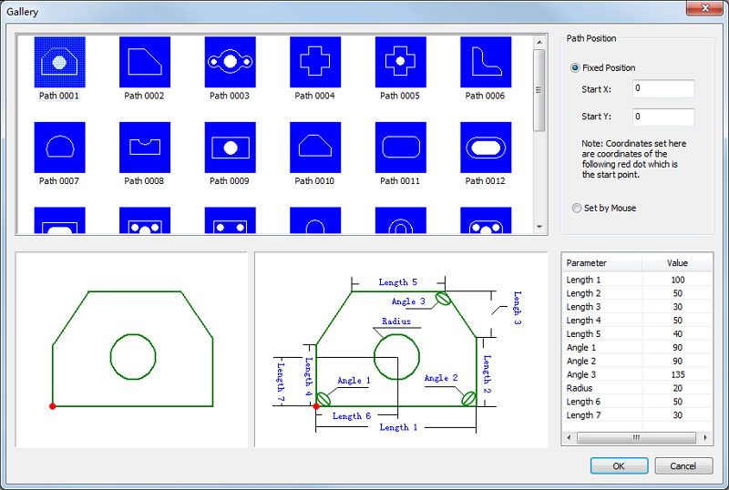
Select the target object.
Set the size and position of the object.
Auxiliary Editing
You can do the following for better effects of object editing:
- Select objects
- Pan the view
- Fit to window
- Zoom in the selected area
- Measure distance
- View objects
- Set catch options
Select Objects
It is used to select objects for editing.
To select objects, do one of the following:
In the left of the function window, to call Select Object command, click
 .
.Do one of the following:
To select a single object, left click the target object on the function window.
To select several objects, press Ctrl and left click the target objects one by one.
To select objects contained in the selected area, hold the left mouse button to drag from the upper left to the lower right.
Objects intersected with the area will not be selected.
To select objects intersected with or contained in the selected area, hold the left mouse button to drag from the lower right to the upper left.
Pan the View
It is used to reposition the function window by selecting a base point and a second point for the new position, and used for a better view of objects without changing the actual sizes and coordinates.
To pan the view, do one of the following:
Press the mouse wheel and drag the mouse at the same time to move the view to the target position.
Click
 to call Pan command, and hold the left mouse button to move the view to the target position.
To stop panning the view, right click or press Esc.
Fit to Window
It is used to resize objects and make them fit to the function window on the premise of showing all objects, and used for a better view of objects without changing the actual sizes and coordinates.
To fit to window, do one of the following:
In the left of the function window, click
 .
.On the numeric keypad, press *.
Zoom in the Selected Area
It is used to zoom in the selected part of the object to the size of the function window, and used for a better view of objects without changing the actual sizes and coordinates.
To zoom in the selected area, do the following:
To call Zoom by Rect command, click
 .
.Left click on the function window, drag the mouse to form a rectangle and left click again. The area formed by the rectangle zooms in.
Measure Distance
It is used to measure distance, X-axis / Y-axis offset and the vector angle between two points.
To measure distance, do the following:
To call Measure command, in the left of the function window, click
 .
.Left click to select the start point for measuring, and move the cursor to select the end point.
The measurement result shows near the end point.
Set Catch Options
It is used to precisely locate feature points and connect objects during drawing an object.
Once the cursor moves close to the feature points, the system can easily locate to the points.
To set catch options, do the following:
To open Catch Options dialog box, in the top of the function window, click
 :
: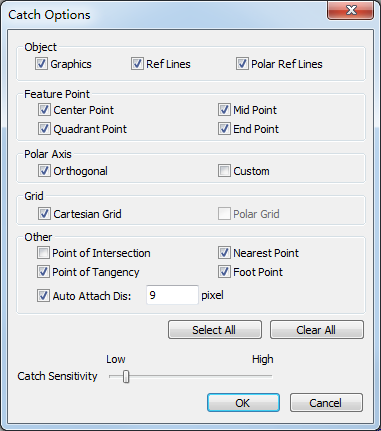
Check the feature items according to the shape of the object.
Adjust the catch sensitivity.
It is easier to get the feature points with higher catch sensitivity.
To enable catching function, in the top of the function window, click
 .
.
Batch Modifying
It is used to modify the target objects and objects with the same shape and size at the same time.
To modify objects in batch, select the target object, and do the following:
To call batch modifying command, right click on the function window, select Batch Modifying.
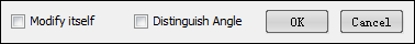
Optional: Do one of the following based on your needs:
To modify the target object only, check Modify Itself:
With it unchecked, the system modifies objects with the same shape and size.
Not to modify objects with the same shape and size but with different rotation angles, check Distinguish Angle.