Quick Start
This section mainly introduces the operations to quickly use Double-tool CNC System for machining.
The process of quick start is as follows:
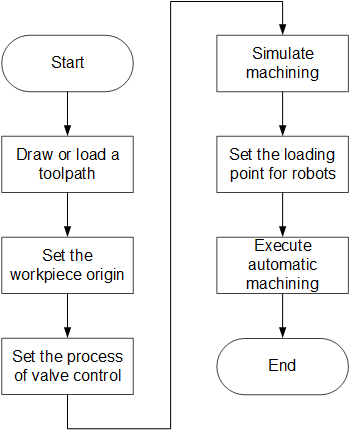
If there is no special instruction, please execute the above operations in Operator page.
Load or Draw a Toolpath
Before machining, you need to load a prepared toolpath or draw a toolpath in the function window.
To load or draw a toolpath, do one of the following:
To load a toolpath, do one of the following:
Drag the target toolpath (supported formats:
NCEX/DXF/DWG/PLT/G/NC) into the function window.To load a
NCEXfile only, do one of the following and select the target tool path file:- In the upper part of the function window, click
 .
. - Click the operational button
 .
.
- In the upper part of the function window, click
To import a
DXF/DWG/PLT/G/NCfile, in the upper part of the function window, click .
.
To draw a toolpath, do one of the following:
The loaded tool path shows in the function window.
Set the Workpiece Origin
This operation is used to set the origin of the workpiece coordinate system (WCS) by clearing workpiece coordinates of each axis, so as to define the coordinate origin in the toolpath file before machining.
To set the workpiece origin, do the following:
Optional: If the target WCS is not the default one, to switch to the target WCS, click Switch WCS in the operation control area.
The system supports WCS G54 and G55. The default WCS is G54.
Select one of the following:
Set X-axis Workpiece Origin
This operation is used to set X-axis workpiece origin by clearing. And it differs in clearing modes.
The clearing mode is defined by parameter Clearing Mode of Double Tools:
0: clear X-axis by space.
This mode only supports clearing X1-axis. The system will automatically calculate X2-axis origin position according to the distance between workpiece origins after clearing X1-axis.
1: clear X-axis independently, that is, separately clear X1-axis and X2-axis.
In this mode, the distance between double tools during machining will keep the value at clearing.
According to the clearing mode, set X-axis workpiece origin:
If parameter Clearing Mode of Double Tools is set to 0, do the following:
To ensure the distance between workpieces, set parameter Distance between Y1Y2 Workpiece Origins(G54) / Distance between Y1Y2 Workpiece Origins(G55) according to the actual situation.
To move X1-axis to the target position, click X1+ / X1- in Manual mode.
To clear X1-axis, click
 . The system clears workpiece coordinates of X1-axis and automatically calculates X2-axis origin position according to the set distance.
Note: The distance between double tools during machining keeps the setting value of parameter Distance between Y1Y2 Workpiece Origins(G54) / Distance between Y1Y2 Workpiece Origins(G55).
If parameter Clearing Mode of Double Tools is set to 1, do the following:
To move X1-axis to the target position, click X1+ / X1- in Manual mode.
To clear X1-axis, click
.To move X2-axis to the target position, click X2+ / X2- in Manual mode.
To clear X2-axis, click
 .
.
Note: During machining, the distance between double tools keeps the value at clearing.
Set Y-axis Workpiece Origin
To set Y-axis workpiece origin, do the following:
To move Y-axis to the target position, click Y+ / Y- in Manual mode.
To clear Y-axis, click
 .
.
Set Z-axis Workpiece Origin
To set Z-axis workpiece origin, do the following:
To move Z1-axis to the target position, click Z1+ / Z1- in Manual mode.
To clear Z1-axis, click
 .
.To move Z2-axis to the target position, click Z2+ / Z2- in Manual mode.
To clear Z2-axis, click
 .
.
Set the Process of Valve Control
This operation is used to define the turning on/off sequence and delay time for valves in the current machining mode.
To set the process of valve control, do the following:
Click
 → Valve Control. Set Valve Control Process dialog box pops up:
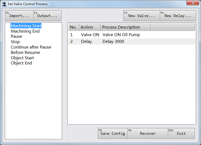
Select the target process on the left, and double click the target action on the right. Edit Valve Process / Edit Delay Process dialog box pops up:
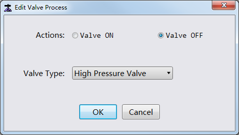
Modify the action type and valve type/ delay time.
Optional: To undo modifications and restore the default, click Recover.
To save modifications, click Save Config.
In Set Valve Control Process dialog box, you can also do the following:
To create a new valve/delay process, click New Valve / New Delay in the upper right.
To import or export a valve/delay process, click Import / Output in the upper left.
Simulate Machining
This operation is used to see the movement of the machine tool in advance, so as to avoid damage to the machine tool due to programming mistakes in the toolpath.
It provides a fast but lifelike simulation machining environment. During simulation, no actual machining occurs, and only the moving track of the tool at a high speed shows in the function window.
To simulate machining, do the following:
To enter into the simulation mode, click Simulate in the operation control area.
In Auto mode, click
 . The system starts to simulate machining.
The simulation track shows in the function window.
Set the Loading Point for Robots
Double-tool CNC System uses robots to load/unload material. This operation is used to set the correct loading point, so as to confirm the safety during loading/unloading material with robots.
The loading point is the same as the fixed point in the system.
To set the loading point for robots, click → Parameters in the upper right, find and set parameter Fixed Point Position.
After setting the loading point for robots, click To FixedPt in the operation control area. The tools move to the loading point, and the robot starts to load material.
Execute Automatic Machining
This operation is used to start machining.
To execute automatic machining, use one of the following modes:
Standard machining mode: to automatically execute machining from the beginning to the end.
Remote machining mode: to automatically execute machining with the assembly line of double stations.
Use the Standard Machining Mode
To execute machining in the standard machining mode, click in Auto mode. The system automatically starts machining.
During machining, you can do the following to control machining:
To stop machining, click
 .
.To pause machining, click
 .
.To resume machining from the exact interrupted position when breakpoint resume or E-stop occurs, click
 .
.
Use the Remote Machining Mode
To use the remote machining mode, do the following:
To enable the remote machining mode, click
→ Parameters in the upper right, find parameter Enable Assembly Line for Machining and set it to Yes.Optional: In cycle machining setting and station selection area, set the cycle times and check 2 Stations to enable double stations.
With 2 Stations unchecked, if left and right stations are both available, the system will use left station for machining by default.
In Auto mode, click
. The system automatically executes machining as follows (taking firstly starting machining on the left station as an example):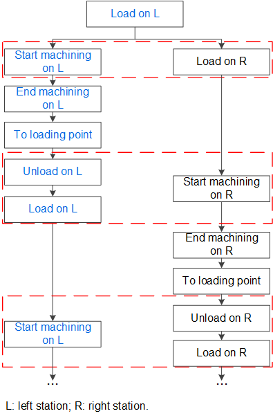
Optional: To manually unload material, click To Load in the operation control mode after unloading material. The system automatically informs the robots to load material again and repeats the above process.
If the machining process ends abnormally and you need to continue machining, click to continue machining.
Note: The system does not exit the remote machining mode during executing breakpoint resume.
To exit the remote machining mode, in Idle status, click  .
.