Main Software Page
According to the operational role and usage scenarios, the software page can be divided into the following:
Operator page (default page)
It includes frequently used operations during machining for operators.
In Technician page, to switch to Operator page, in the menu bar, click System → Operator Page.
-
It includes rich operations and machine parameters for technicians to debug the machine tool.
In Operator page, to switch to Technician page, click
 → Technician.
Operator Page
Operator page is shown as follows:
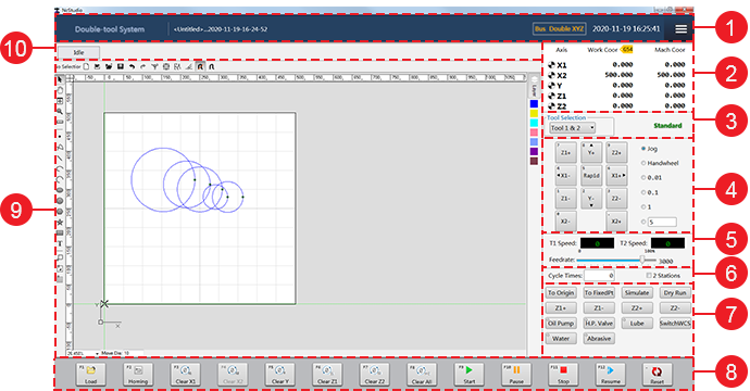
- Title area
- Axis coordinate display area
- Tool selecting and machining mode display area
- Axis direction and mode selecting area
- Speed control area
- Cycle machining setting and station selection area
- Operation control area
- Operational buttons
- Function window
- CNC status area
Title Area
This area consists of the system name, current file name, current configuration, current date and time, and burger button .
Among them, burger button is used to do the following:
- Set parameters.
- Control valve.
- Switch to Technician page.
Axis Coordinate Display Area
This area shows the machine coordinates and workpiece coordinates of each axis.
After each axis returns to the machine origin, the sign  will appear in front of each axis in this area.
Tool Selecting and Machining Mode Display Area
This area is used to do the following:
Select tools for machining. See Select the Tool(s) for details.
Show the current machining mode. See Execute Automatic Machining for how to switch the machining mode.
Axis Direction and Mode Selecting Area
This area consists of the following:
Axis direction buttons: to move each axis towards positive/negative direction.
Note: The axis number controlled by axis direction buttons differs in the selected tool number.
Mode buttons: to switch to the following modes:
Jog
- Press an axis direction button. The machine tool keeps running at jogging speed until you release it.
- Press several axis direction buttons. The selected axes move at the same time at jogging speed until you release them.
- Press Rapid button and an axis direction button at the same time. The machine tool moves at rapid jogging speed until you release them.
HW: the machine tool is controlled by the handwheel.
Step: click an axis direction. The machine tool moves 0.01mm, 0.1mm, 1mm or the customized step size.
The default customized step size is 5mm and the customized step should not be too large to avoid damage due to misoperation.
Note: Please do not click the axis direction button too frequently because the system needs a certain time for response.
Speed Control Area
This area consists of the following:
Current actual speed: to show the current actual speed of tool 1 and tool 2.
Feedrate override: to adjust the feedrate override.
Cycle Machining Setting and Station Selection Area
This area is used to do the following:
Set the machining times for cycle machining.
After the set times has reached, the machine tool automatically stops machining.
Enable double stations for machining.
With it unchecked, the system uses the current station for machining by default.
Operation Control Area
This area is used to do the following:
Execute common operations, including returning to the machine origin, returning to the fixed point, simulate machining, execute dry run, execute Z-axis jiggle, and switch the workpiece coordinate system.
Turn on/off common ports, including the oil pump, high pressure valve, lube valve, water valve, and abrasive valve.
Operational Buttons
The operational buttons include buttons for unloading a machining file, returning to the machine origin, clearing all axes, starting machining, pausing machining, stopping machining, resuming machining and reset machining.
Function Window
This window is used to do the following:
- Draw objects.
- Edit objects.
- Set batch modifying.
- Set technics.
- View the machining track in real time during machining to ensure the proper implementation of the toolpath file.
CNC Status Area
This area is used to check the following:
Current system status, including Idle, Run, etc.
System prompts and alarms.
You can check system logs in Log dialog box by double clicking the blank area. See Check System Logs for details.
Technician Page
Technician page is shown as follows:
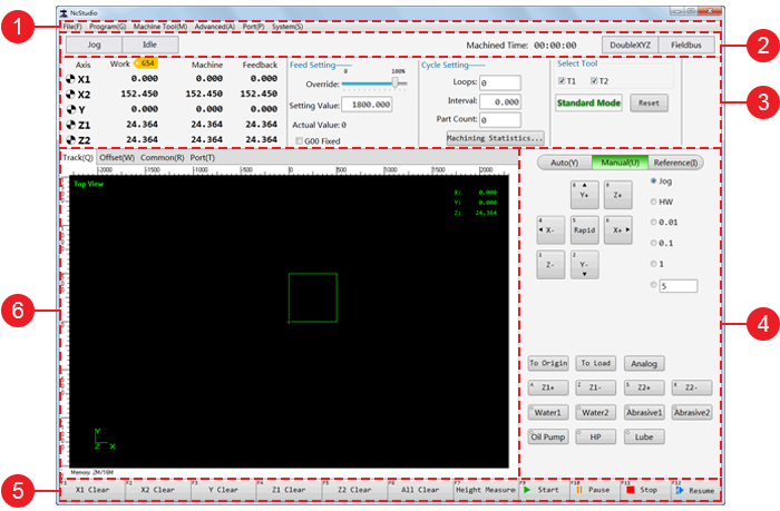
- Menu area
- CNC status area
- Machine control area
- Mode control area
- Operational buttons
- Function windows
Menu Area
This area includes the following menus:
File: load a toolpath, generate an installation package, restart the software, restart/close the system, and show the desktop.
Program: check machining statistics.
Machine: execute operations about the machine tool, including start standard machining, simulate machining, return to the machine origin, execute Y1-axis and Y2-axis jiggle, etc.
Port: turn on the water pump, oil pump, high pressure pump, water valve, abrasive valve, and set valve control process.
System: check system logs, set system parameters, set drive parameters, clear the drive alarms, switch to Operator page, use remote assistance, etc.
CNC Status Area
This area is used to check the following:
Current system mode, including Auto, Jog, etc.
Current system status, including Idle, Run, etc.
System prompts and alarms.
You can check system logs in Log dialog box by double clicking the blank area. See Check System Logs for details.
Machined time
Current software configuration
Machine Control Area
This area consists of the following:
Coordinate display area: to show the current active workpiece coordinate system, workpiece coordinate and machine coordinate of each axis.
Feed setting area: to set feedrate override, and modify speed.
Cycle setting area: to set cycle times and interval, check finished cycle times, workpiece count and machining statistics, and enable double stations for machining.
Tool selection and machining mode display area: to select the tool(s), and display the current machining mode.
Mode Control Area
This area consists of the following modes:
Auto mode:
Show the content of the loaded toolpath file.
Execute common operations, including returning to the workpiece origin, returning to the fixed point, execute dry run, reset machining, and execute Z-axis jiggle.
Turn on/off common ports, including oil pump, high pressure valve, lube valve, water valve, and abrasive valve.
Manual mode:
Show axis direction buttons and mode buttons. See Axis Direction and Mode Selection Area for details.
Execute common operations, including returning to the workpiece origin, returning to the fixed point, execute dry run, and switch the workpiece coordinate system.
Turn on/off common ports, including oil pump, high pressure valve, lube valve, water valve, and abrasive valve.
Reference mode:
Set the feedback position of the absolute encoder as datum.
Adjust the machine coordinates of the software after getting the feedback position of the absolute encoder.
Function Windows
Function windows include the following:
Track window: to show the machining track in real time during machining, or dry run.
Common Parameters window: to check, modify and customize common parameters.
Port window: to check and modify the port polarity, conduct a simulation test, and set filter.