Special Operations
This section mainly introduces special operations in Double-tool CNC System.
Special operations mainly include the following:
- Select the tool(s)
- Execute Z-axis jiggle
- Execute Y1-axis and Y2-axis jiggle
- Use remote assistance
- Set safety light curtains
- Start machining from the positioning point
- Optimize acceleration/deceleration at corners
Select the Tool(s)
It is used to choose the tool(s), which is convenient to execute adjustment and use another tool to continue cutting in case of something wrong with one tool.
Before selecting the tool(s), set parameter Min Distance between X1 and X2 and Max Distance between X1 and X2 to protect tools from collision.
To select the tool(s), select the tool(s) in Tool Selection area in Operator page or Technician page:
Select tool 1 or tool 2
During manual movement, only the selected tool moves.
During automatic machining, the double tools move synchronously, but the unselected tool does not do cutting actions and its Z-axis does not move for safety.
Select tool 1 and tool 2
During manual movement, the double tools move at the same time.
During automatic machining, the system synchronizes the workpiece coordinates of the double tools and keeps synchronous cutting.
Execute Z-axis Jiggle
It is used to adjust height of the tool, so as to find the best cutting height.
Before executing Z-axis jiggle, make sure the system is in Running or Pause status.
To execute Z-axis jiggle, do the following:
To open Parameter dialog box, do one of the following:
In Operator page, click
 → Parameters.
In Technician page, click System → Parameters.
Set the following parameters:
Jiggle Distance(Z1) / Jiggle Distance(Z2): the moving distance of the machine tool corresponding to each jiggle.
Jiggle Speed(Z1) / Jiggle Speed(Z2): the speed during jiggle.
To adjust the tool to the best cutting height, click Z1+ / Z1- / Z2+ / Z2- in the operation control area.
Execute Y1-axis and Y2-axis Jiggle
It is used to eliminate offset and reset datum of Y-axis when offset exists in the machine coordinates of Y1-axis and Y2-axis, so as to simplify operation and save time.
It is only available to machine tools with diverter double Y whose Y1-axis and Y2-axis motors are connected to two separate interfaces of the terminal board.
To execute Y1-axis and Y2-axis jiggle, do the following in Technician page:
To open Y1Y2 Jiggle dialog box, in the menu area, click Machine → Y1Y2 Jiggle, and turn switch Disable Double Y Adjustment to ON status:
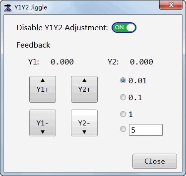
Select or customize a step size.
According to Y1-axis and Y2-axis offsets, click Y1+ / Y1- / Y2+ / Y2- to move Y1-axis or Y2-axis.
Use Remote Assistance
It is used to use remote assistance to control your system, which is good for commissioning and troubleshooting.
Before using remote assistance, make sure the system has been networked.
To use remote assistance, do the following in Technician page:
In the menu area, click System → Remote Support. The following dialog box pops up:
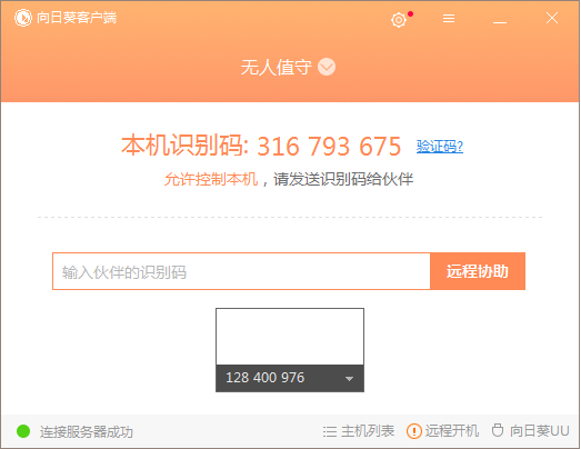
Send the identification code to someone who can help.
Set Safety Light Curtains
It is used to set safety protection around the machine tool, so as to avoid that outside objects enter into the machine tool during running.
To set safety light curtains, do the following:
To open Parameters dialog box, do one of the following:
- In Operator page, click → Parameters.
- In Technician page, click System → Parameters.
- In Operator page, click
Select Manufacturer permission, find and set parameter Lower Limit of Safety Grating and Upper Limit of Safety Grating.
When tool 1 and tool 2 both move out of the set area of safety light curtains, the system automatically enters into Pause status and locks the screen to avoid accident.
Start Machining from the Positioning Point
It is used to cut the toolpath from the target position to the end of the toolpath again after machining finishes, if you are not satisfied with the machining result.
With the selected point on the function window as the circle center, the system draws circles whose radius is within 15mm. The point nearest to the circle on the graph is the positioning point.
To start machining from the positioning point, do the following in Operator page:
Select a point near the graph on the function window.
Right click, and do one of the following:
If you are not sure whether the positioning point is as expected, select Locate to Here to check the positioning point, and select Start Machining from Here if it is as expected.
If you are sure the positioning point is as expected, select Start Machining from Here.
The system starts machining from the positioning point.
Optimize Acceleration/Deceleration at Corners
It is used to optimize the cutting effect at corners for cutting thick metal.
To optimize acceleration/deceleration at corners, do the following:
To open Parameter dialog box, do one of the following:
In Operator page, click
→ Parameters.In Technician page, click System → Parameters.
Select the manufacturer permission, set and find the following parameters:
Acc and Dec at Inflection Point: whether to accelerate and decelerate at inflection point.
Speed Rate at Corner: to control the cutting speed at corners, it equals to the cutting speed times the percent of speed at corners.
Accelerating Distance at Inflection Point: how far from the inflection point to start accelerating after the corner is cut.
Decelerating distance at Inflection Point: how far from the inflection point to start decelerating when the system is to cut the corner.
Decelerating Distance for Last Segment: the decelerating distance for the last segment of object.
Min Angle to Decelerate at Corner: only when angle at corner is greater than the minimum deceleration angle at the inflection point, the speed at corners is available.