Technics
This section introduces technics you can set in Double-tool CNC System.
If there is no special instruction, please set technics in Operator page.
Add a Chamfer
It is used to add chamfers to objects whose angles are less than 180°, so as to improve cutting effect on corners of thick material.
To add a chamfer, select the target object, and do the following:
To open Chamfer dialog box, right click on the function window, and select Chamfer:
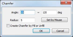
Set parameter Angle and Radius.
Optional: To automatically add chamfers for closed objects according to the attribute of fill/unfill, check Create Chamfer by Fill or Unfill.
The system automatically adds a chamfer at the angle that meets the demand.
Taking setting parameter Angle to 45°~90° and checking Create Chamfer by Fill or Unfill as an example, the result is as follows:
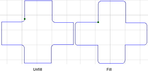
Set Unfill or Fill
It is used to reserve a certain part of closed objects. For objects with Unfill attribute, the system reserves the outer part; for objects with Fill attribute, the system reserves the inner part.
To set unfill or fill, select closed objects, and do the following:
Right click on the function window, and click Unfill/Fill.
Select one of the following:
To manually set the selected objects as unfill/fill, select Unfill / Fill.
To set the selected objects as unfill by default, select Auto Setting.
Set a Lead Line
It is used to avoid machining errors or damage to the workpiece caused by laser staying above the start position for a long time, so as to improve machining accuracy.
The type of lead line differs in the leading direction:
Lead-in line: consisting of line lead line, arc lead line and hook lead line.
Lead-out line: consisting of line lead line and arc lead line.
To set a lead line, select the target object, and do the following:
To open Set dialog box, right click on the function window, select Lead Line → Set.
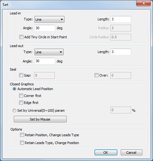
Select a type for the lead line according to the cutting technics.
Set related parameters of the lead line.
See Parameters for details.
Optional: If the target object is a closed object, in Seal area, select one of the following:
Gap: The lead line is unclosed and the cutting head will not cut through at the sealing position.
Over: The lead line is closed and the cutting head will cut at the sealing position.
Set the position of the lead line:
If you check Automatic Lead Position, do one of the following:
To automatically set the lead line at the position with a larger angle in the object, check Corner first.
To automatically set the lead line at the longest edge of the object, check Edge first.
If you check Set by Universal (0~100) param. The position of the lead line is the set ratio times the total length.
If you check Set by Mouse, click on the edge of the object after the cursor turns into
 to specify the position of the lead line.
In Options Area, select one of the following:
Retain Position, Change Leads Type
Retain Leads Type, Change Position
Optional: Manually modify the lead line:
To call Start Point command, Right click on the function window, select Lead Line → Set Start Point.
Do one of the following:
To modify the position of the lead-in line, left click on the edge of the object.
To draw a line-type lead-in line from outside to the edge on the object, left click on the outside and the edge of the object.
The result is as follows:

Parameters
Angle: For a line-type lead line, it refers to the angle between the lead line and the tangent line of the intersection; for an arc-type lead line, it refers to the central angle.
Length: For a line-type/arc-type lead line, it refers to the length of the line/arc; for a hook-type lead line, it refers to the sum of the radius of the arc and the length of the line.
Radius: For a hook-type lead line, it refers to the radius of the arc.
Add Tiny Circle in Start Point: Add a tiny circle at the start point of the lead-in line, so as to solve the problem that the accumulation of slag influences cutting effect during piercing a thick tube.
Circle Radius: The radius of the hole at the start point of the lead line.
Set Kerf Compensation
There exists deviation between the sizes of actual cutting parts and theoretical ones, which is caused by the kerf during cutting. The deviation leads to a smaller size in the outer contour and a larger size in the inner contour. This operation is used to compensate the deviation.
The type of kerf compensation includes the following:
All shrink: shrink the cutting area for all selected parts.
All expand: expand the cutting area for all selected parts.
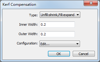
Unfill: shrink; fill: expand: shrink the cutting area for parts with unfill attribute, and expand the cutting area for parts with fill attribute.
To compensate the kerf, select the closed objects, and do the following:
To open Kerf Compensation dialog box, right click on the function window, and select Kerf Compensation:
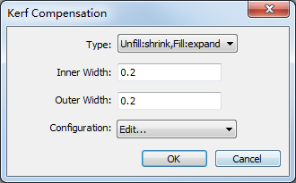
Select a compensation type.
Set the inner width and outer width.
Optional: To save the commonly used inner width and outer width for later use, do the following:
In the drop-down box of Configuration, select Edit. Configuration dialog box pops up:
Click Add, set a name in Description column, set the inner width in Inner Width column, and set the outer width in Outer Width column.
For later use, in the drop-down box of Configuration, select the set name. The system automatically fills in the inner width and outer width.
Change the Machining Order
It is used to change the machining order. After drawing several objects, the default machining order is the drawing order.
Before changing the machining order, to show the machining order, in the top of the function window, click  .
.
To change the machining order, do one of the following:
- Automatically change the machining order
- Manually change the machining order
- Specify the machining order for a single object
- Change the machining order in a list
- Change the machining order by manual drawing
- Sort to the top or bottom
Automatically Change the Machining Order
The system automatically sorts objects according to the selected sorting strategy.
To automatically change the machining order, select the target objects, and do the following:
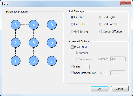
To open Sort, right click on the function window, and select Machining Order → Auto Sort:

In Sort Strategy area, select a sorting strategy.
In Advanced Options, check advanced option(s):
Divide Grid
AutoSet: to automatically divide objects into the same group based on the distance and count.
Fixed Value: the objects whose distance is less than the set value will be divided into the same group.
Color: to sort objects in the part according to the layer order. It only applicable to the part with nested relation.
Small Objects First: to sort objects whose sizes are less than the set value. It only applicable to part interior with nested relation.
Sort in Group: to sort objects in groups according to the sort strategy.
To separately set the order for the objects in a group, right click on the function window, click Machining Order → Sort within Group, and select a sorting strategy and advanced option(s) in Sort dialog box:
Manually Change the Machining Order
It is used to manually specify the machining direction for a single object or several objects.
To manually change the machining order, do the following:
To call Manual Sorting command, do one of the following:
Select the target objects, right click on the function window, and select Machining Order → Manual Sort.
Right click on the function window, and select Manual Sort.
The cursor turns into
 , and the system automatically shows the machining order.
Select the first target object.
The cursor turns into
 . The machining order on the object turns into 1, and the order of other objects turns into 2,3 ... in sequence on the basis of the previous order.
To reset the last order number, right click and select Previous Order.
Repeat step 2 and click the objects in order.
If you need to exit manual setting tool, do one of the following:
- Right click and select Exit.
- Press Esc.
Specify the Machining Order for a Single Object
It is used to specify the machining order for a single object.
To specify the machining order for a single object, select a single object, and do the following:
To open Specify Order Separately dialog box, on the function window, right click and select Machining Order → Specify Order:
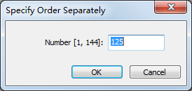
To specify an order, enter an order in Number [1, n] input box.
n is the maximum machining order in the toolpath.
Change the Machining Order in a List
Each object has a number. This operation is used to manually change the machining order according to the number.
To change the machining order in a list, do the following:
Select an object.
To open Order List dialog box, on the function window, right click and select Machining Order → Order List:
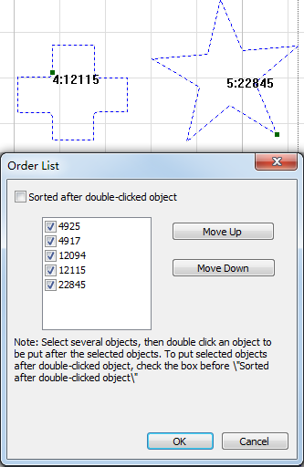
Check the object, and do one of the following to sort the machining order:
Click Move Up/Move Down to move the object.
Double click another object to move the checked object to the clicked position.
Change the Machining Order by Manual Drawing
It is used to manually change the machining order of two objects, and then change the whole machining order.
To change the machining order by manual drawing, select the target objects, and do the following:
To call Manual Draw Sorting command, do one of the following:
Right click on the function window, click Machining Order → Draw Connection Line.
Select no object, right click on the function window, click Draw Connection Line.
Select a single object. The object is highlighted.
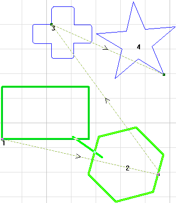
Hold the left button, draw a line from the object, connect it to another object (the target object), and release the mouse until the target object is highlighted.
The machining order of the target object is behind the selected object at the first time.
After changing the machining order by manual drawing, to exit Manual Draw Sorting command, right click and select Exit, or press Esc.
Sort to the Top or Bottom
It is used to turn the machining order of a single object to the top or bottom.
To sort to the top or bottom, select a single object, Right click on the function window, and select Machining Order → Sort to Top / Sort to Bottom.
Change the Machining Direction
It is used to change the machining direction for all closed objects. After drawing an object, the default machining direction is counterclockwise.
Before changing the machining direction, to show the machining direction, in the top of the function window, click  .
.
To change the machining direction, select the target object(s), and do the following:
To open Mach Direction dialog box, right click on the function window, select Machining Direction → Set:
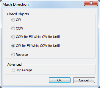
Select the machining direction based on your needs.
Alternatively, if you just need to reverse the machining direction, do one of the following:
Right click on the function window, select Machining Direction → Reverse.
In Mach Direction dialog box, select Reverse.
Optional: To skip the machining direction of groups, in Advanced area, check Skip Groups.
Set Punching Parameters
Waterjet cutting uses high-speed and high-energy water current to cut material. Before feeding motion, the water current should penetrate the material. For hard and thick material, this cutting method can help to improve the machining efficiency and save material in a great extent.
To set punching parameters, select the target object, and do the following:
To open Punch dialog box, in the left of the function window, click
 :
: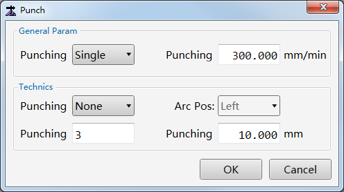
In General Param area, set the following parameters:
Strategy: it includes the following:
Single punching: during cutting multiple objects, each object is punched and cut before cutting the next one.
Batch punching (only support NCE file): during cutting multiple objects, all objects are punched first before cutting them.
Speed: The speed for punching.
In Technics area, set the following technics:
Type
Arc punching: circle is punched at the start point of the lead line.
Swing punching: straight-line is punched at the start point of the lead line.
Arc Pos
Left: the circle is on the left of the start point of the lead line.
Middle: the circle is at the middle of the start point of the lead line.
Right: the circle is on the right of the start point of the lead line.
Times: the machining times of circle for arc punching, and the swinging times of straight-line for swing punching.
Distance: the punching diameter for arc punching, and punching interval for swing punching.
Set Cutting Speed
It is used to set the cutting speed for the target layer so as to set the cutting speed for objects in the layer.
In the left of the function window, click ![]() and set the cutting speed for the target layer in Layer Setting dialog box.
and set the cutting speed for the target layer in Layer Setting dialog box.
Set the Berth Point
A point on the target object will coincide with the workpiece origin according to the set berth point. For example, if the berth point is set as bottom left, the upper right corner of the target object will coincide with the workpiece origin.
It is used with the operation of setting the workpiece origin.
To set the berth point, do the following:
To open Set Berth Point dialog box, in the left of the function window, click
 :
: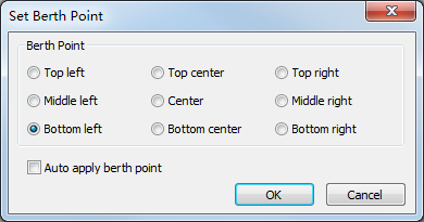
Select the berth position.
Optional: To automatically make the object move to the workpiece origin by the set berth point when the workpiece origin is set again, check Auto apply berth point.
Do Clearing
It is used to clear some set technics, including lead line, kerf compensation and punching.
To do clearing, select the target object, right click on the function window, click Clear → Lead Line / Kerf Compensation / Punch.