Set Tool Parameters
You can use the software to manage the tools effectively to improve machining efficiency.
Tool parameters include
Set Tool Compensation Parameters
Used to compensate the difference between the actual tool position and the programmed tool position.
After the tool compensation parameters are set, if a tool is replaced, you only need to change the tool compensation value instead of modifying the machining program.
Follow the steps below to set tool compensation parameters:
In the menu bar, go to System > Global Parameters. In the Param window, click the first drop-down menu in the lower-left corner and select Manufacturer. Set the parameters Enable Tool Length Compensation and Enable Tool Radius Compensation to Yes.
In the menu bar, go to Operation > Tool setting.
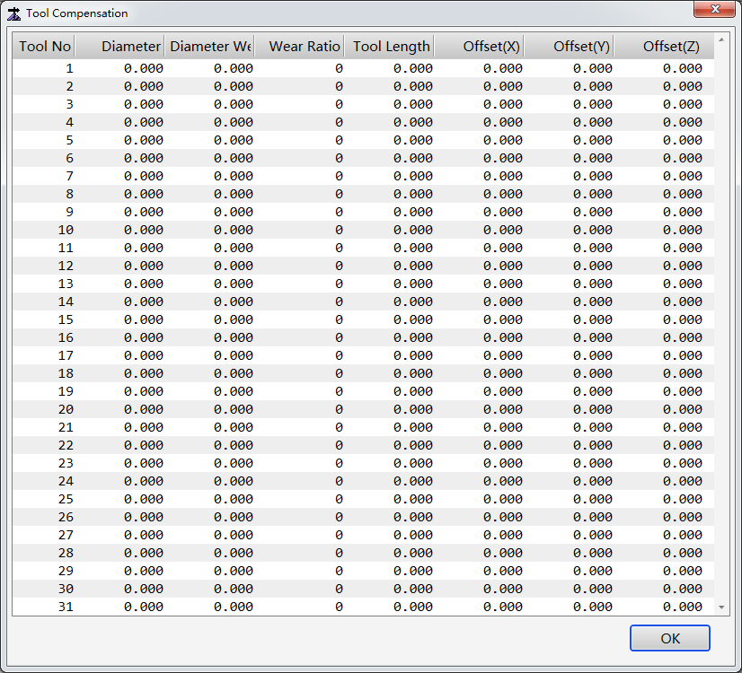
In the Tool Compensation window, double-click the target field. Enter a value in the input box.
Parameter Description Tool No. The tool sequential number. At most 31 tools are supported. Diameter Used for radius compensation. Diameter Wear Used for worn diameter compensation. Wear Ratio Indicates the worn diameter amount every time the tool processes 1-meter materials. Applicable to real-time wear compensation. Offset(X)/(Y)/(Z) Indicates the tool offset value. Manually enter a value in the field or use a tool sensor. Click OK.
Set Wear Compensation Parameters
If the wear compensation function is enabled, the system makes real-time adjustment of the tool feed amount based on the wear amount.
Wear compensation is not needed during cutting.
If the wear compensation function is enabled, the tool radius will have a certain deviation. You need to check to see if such deviation causes any intervention.
Follow the steps below to set wear compensation parameters:
In the menu bar, go to System > Global Parameters. In the Param window, change the status of Enable Tool Radius Compensation and Enable wear compensation based on the description below:
Enable Tool Radius Compensation Enable Wear Compensation Description No Yes Real-time tool wear compensation is disabled. Yes No Real-time tool wear compensation is disabled. Tool compensation for general cases is used. Yes Yes If tool diameter compensation commands G41/G42 is not included in the machining program, real-time tool wear compensation will not be enabled. If the wear compensation conditions are not met, a prompt indicating that the tool diameter is too short will be displayed.
Set the parameter Enable Tool Length Compensation based on the actual situation.
Load programs with G41/G42/G40 tool diameter compensation commands.
Click
 to start machining.
After the G41/G42 commands are processed, real-time tool diameter wear compensation is enabled.
After the G40 command is processed, real-time tool wear compensation is disabled.
Click
 or
or  to save the file in the original path or another path.
The system determines if wear compensation will be enabled based on the wear ratio. If the wear ratio is not 0, wear compensation will be enabled.
Set Tool Offset Parameters
Used to make sure that the tools are lowered to the correct height during machining.
You can set the tool offset parameters with the following methods:
Enter the Z-axis offset value.
Use the current point Z-axis mechanical coordinate as the Z-axis offset.
Use the tool calibration result as the Z-axis offset.
Follow the steps below to enter the offset value:
In the menu bar, go to Operation > Tool setting to open the Tool Compensation window:
Double-click the Offset(Z) field of the target tool and enter the Z-axis offset value in the input box.
Click OK.
Follow the steps below to use the current Z-axis mechanical coordinate as the Z-axis offset:
In the menu bar, go to Operation > Tool calibration setting to open the Tool calibration setting window:
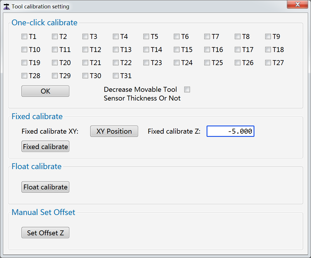
Click Set Offset Z in the Manual Set Offset area to set the Z-axis offset of the current tool to the current Z-axis mechanical coordinate.
Follow the steps below to use the tool calibration result as the Z-axis offset:
In the menu bar, go to Operation > Tool calibration setting to open the Tool calibration setting window:
Optional: If Decrease Movable Tool Sensor Thickness Or Not is ticked, the Z-axis offset value will be the calibration result minus the tool sensor thickness.
Execute tool calibration based on your needs:
To execute tool change and calibration for multiple tools:
A. Tick the target tool numbers in the One-click calibrate area.
B. Click OK. The system will write the calibration results of the selected tools into their Z-axis tool offset.
To execute tool calibration at a fixed point on the machine for a single tool:
A. Control the X axis and Y axis to move above the tool sensor. Click XY Position.
B. Enter a value in the Fixed calibrate Z field.
C. Click Fixed calibrate.
The system will write the calibration result of the selected tool into its Z-axis tool offset.