Common Operations
This chapter mainly introduces the following common operations of NcStudio V10:
Set Parameters
Parameters are divided into three kinds:
- Operator parameters: to view operater parameters, click Operator.
- Manufacturer parameters: to view manufacturer parameters, enter password.
- Developer parameters: only WEIHONG personnel have permission to adjust and modify developer parameters.
To set parameters, do the following:
Click Parameter in tool bar. A dialog box named Parameter pops up:

Click Operator/Manufacturer/Developer to switch to corresponding page.
Double click target parameter.
Enter the value. Click OK.
Pay attention to Effective time:
- If it is Immediately, setting above takes effect immediately.
- If it is After restarting, setting above takes effect after the software is restarted.
- If it is After reloading, setting above takes effect after the program is reloaded.
Commission Encoder Latch
Encoder latch is used to adjust functions of returning to machine origin, edge finding and scan edge. It supports servo drives of both bus-type and pulse-type.
Before commissioning, do the following:
Confirm that the drive is servo drive.
To adjust returning to machine origin function, confirm that the encoder is incremental encoder.
Before executing edge finding and scan edge, confirm that each axis has returned to machine origin and been set datum.
Commission Encoder Latch of Bus Type Servo Drive
To commission, do the following:
Establish communication among axes. Set station address and drive type.
Please refer to Set Bus Function for details.
Set the following parameters according to actual situation:
- N10000~10003 Axis direction
- N11160~11163 Screw pitch
- N11200~11203 Numerator of mechanical reducer ratio
- N11200~11213 Denominator of mechanical reducer ratio
- N16020~16023 Encoder digit
- N16030~16033 Numerator of electronic gear ratio
- N16040~16043 Denominator of electronic gear ratio
- N11001 Encoder type
Modify the value of parameter N11020 Enable encoder locker to Yes.
Restart NcStudio software and drive.
After commissioning, returning to machine origin and edge finding will be executed by latch.
Commission Encoder Latch of Non-Bus Type Servo Drive
To commission, do the following:
Set drive parameters according to actual situation.
Taking YASKAWA driver as an example, set parameters in the table below:
Drive parameter Set value Software parameter Rule PN000 0010(CCW)
0011(CW)Encoder type Modify according to set value of drive parameter. PN002 0100(incremental type) Axis direction Modify according to right-handed coordinate rule. PN200 0005(Pulse equivalent, Pulse direction, Negative logic) Axis encoder direction Opposite to axis direction. PN20E 16777216(Numerator of electronic gear ratio) Screw pitch Modify according to the data of axis that corresponds to the machine. PN210 Pitch/(Pulse equivalent*Mechanical reducer ratio) Mechanical reducer ratio Modify according to the data of axis that corresponds to the machine. PN212 2500 PG frequency dividing ratio 10000; four times PN212 of the drive PN50A 8100 Motor rotational mode(CCW, CW) Modify according to the value of PN000 of the drive. PN50B 6548 Whether the rotational directions of Y1-axis and Y2-axis motors are the same Modify according to machine structure. Execute returning to machine origin for all axes.
Please refer to Return to machine origin for details.
Click Machine Tool → Set Datum. A dialog box named Set Datum pops up:

Enable latch for target axis.
Move the axis manually, and check whether machine coordinate and Feedback coordinate of the axis are the same.
- Same: Feedback coordinate is correct.
- Different: Feedback coordinate is incorrect. Check whether the parameters are set according to the rule.
Set the value of parameter N11020 Enable encoder locker as Yes.
After commissioning, returning to machine origin, edge finding and scan edge will be executed by latch.
Execute Edge Finding
Edge finding function can be used in two situations:
To adjust the coordinate of target graphic when the material is deflected.
To confirm the position on workbench.
To execute edge finding function, do the following:
Click EdgeFinder in tool bar. A dialog box named EdgeFinder pops up:

For successful edge finding, confirm the following:
The rotation angle between the new workpiece coordinate system and the original one cannot exceed 15°.
The new origin cannot be between point A and point B.
Enter the value in the dialog box. Click OK.
Click Load in tool bar, and select the toolpath file.
Click
 . Edge finding starts.
Execute Scan Edge
Scan edge is used to scan glass contour with laser head, and generate a DXF toolpath file which will be edited in CAD.
This function is beneficial to improve efficiency and save cost.
There are two kinds of scan edge function:
- Common function
- Advanced function
To execute scan edge function, do the following:
Place the workpiece on the machine.
Click Scan in tool bar. A dialog box named Irregular Shape Scanning pops up:
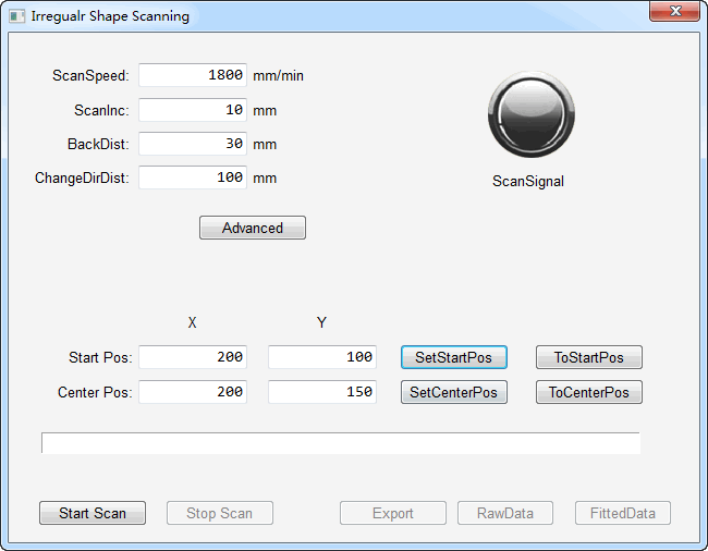
Optional: Click Advanced. Related partameters display in the dialog box.
Set Scan Speed and Scan Inc according to the size of the workpiece.
To avoid triggering limit during scanning, confirm sufficient space for workpiece.
Click To Center Pos to check whether current midpoint is proper.
- Proper: Click Set Center Pos.
- Improper: Move the spindle of the machine to make the laser head shine in the middle of the workpiece. Click Set Center Pos.
Click To Start Pos to check whether current start point is proper.
- Proper: Click Set Start Pos.
- Improper: Move the spindle of the machine to make the laser head shine on the edge of the workpiece. Click Set Start Pos.
Click Start Scan. Scanning starts.
Export scanning result in one of the following ways:
Export: Output a DXF file in which all points are connected with lines.
Raw Data: Output a DXF file in which points are fitted to lines and arcs. Adjust by modifying Cor Index in Advance parameter.
Fitted Data: Output a DXF file in which all points are in it.
Use Wizard
There are three functions of wizard:
Generating three kinds of toolpath files:
- Line cuttig
- Circle cutting
- Region cutting
Using Command cutting
Selecting graphics from Gallery
To use wizard function, do the following:
Click Wizard in function window to switch to wizrd interface.
Select one of the following cut modes:
Set parameters in Parameter Setting area.
Click Load in tool bar.
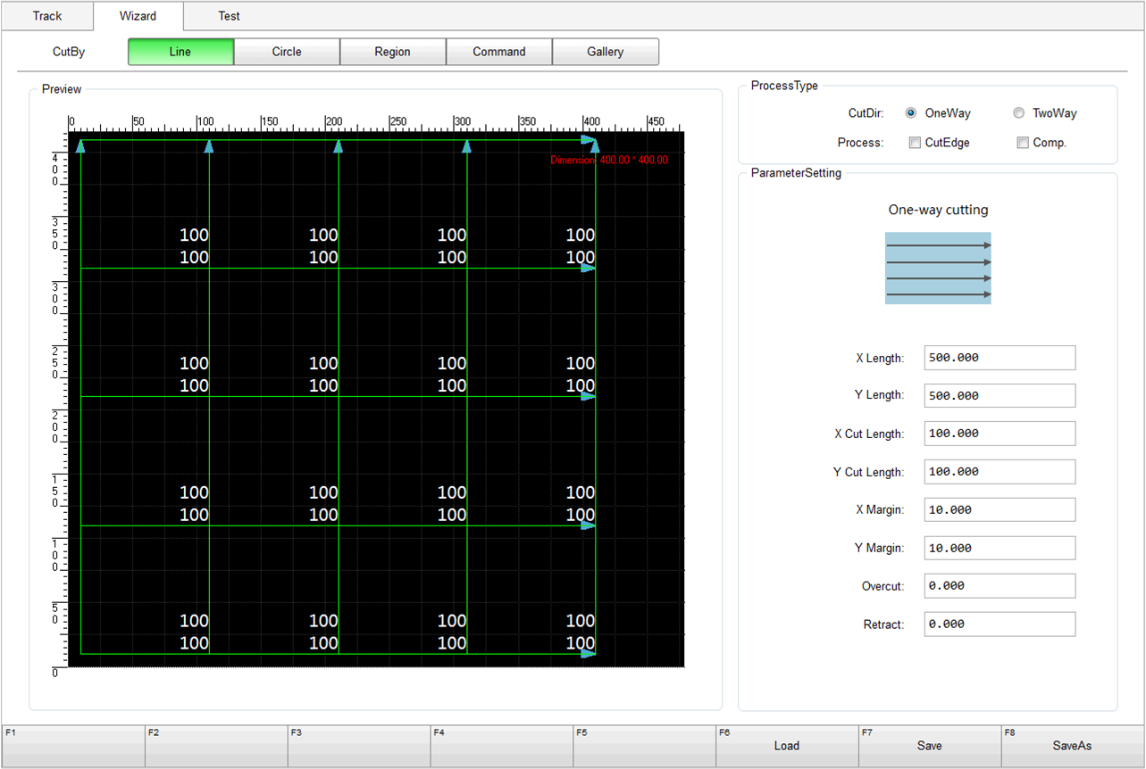
Use Line Cut Mode
Line cut mode supports loading file to machine after editing line cutting toolpath.
The following figure is line cut mode wizard interface:
| Parameter | Description |
|---|---|
| X/Y Length | Length of material in X-axis/Y-axis direction. |
| X/Y Cut Length | Per unit length of material in X-axis/Y-axis direction. |
| X/Y Margin | Distance between the first edge and workpiece. |
| Overcut | Cut allowance that exceeds effective distance. Used to decide the end point for tool and avoid damaging glass within effective distance. |
| Retract | Cut allowance ahead effective distance. Used to decide the start point for tool and avoid damaging glass within effective distance. |
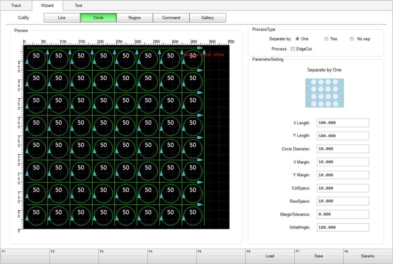
Use Circle Cut Mode
Circle cut mode supports loading file to machine after editing circle cutting toolpath.
The following figure is circle cut mode wizard interface:
| Parameter | Description |
|---|---|
| Circle Diameter | The diameter of circle that has been cut out from material. |
| X/Y Margin | Distance between the first edge and workpiece. |
| ColSpace | Distance between circles in X-axis direction. |
| RowSpace | Distance between circles in Y-axis direction. |
| Margin Tolerance | Cut allowance of material in Y-axis direction. X-axis single cutting line will be generated only when the distance between the edge of the last line of circles and workpiece origin. |
| Initial Angle | Angle offset of plunge position. |
Region Cut Mode
Region cut mode supports editing different objects in different areas on material and loading to machine it.
The following figure is circle cut mode wizard interface:
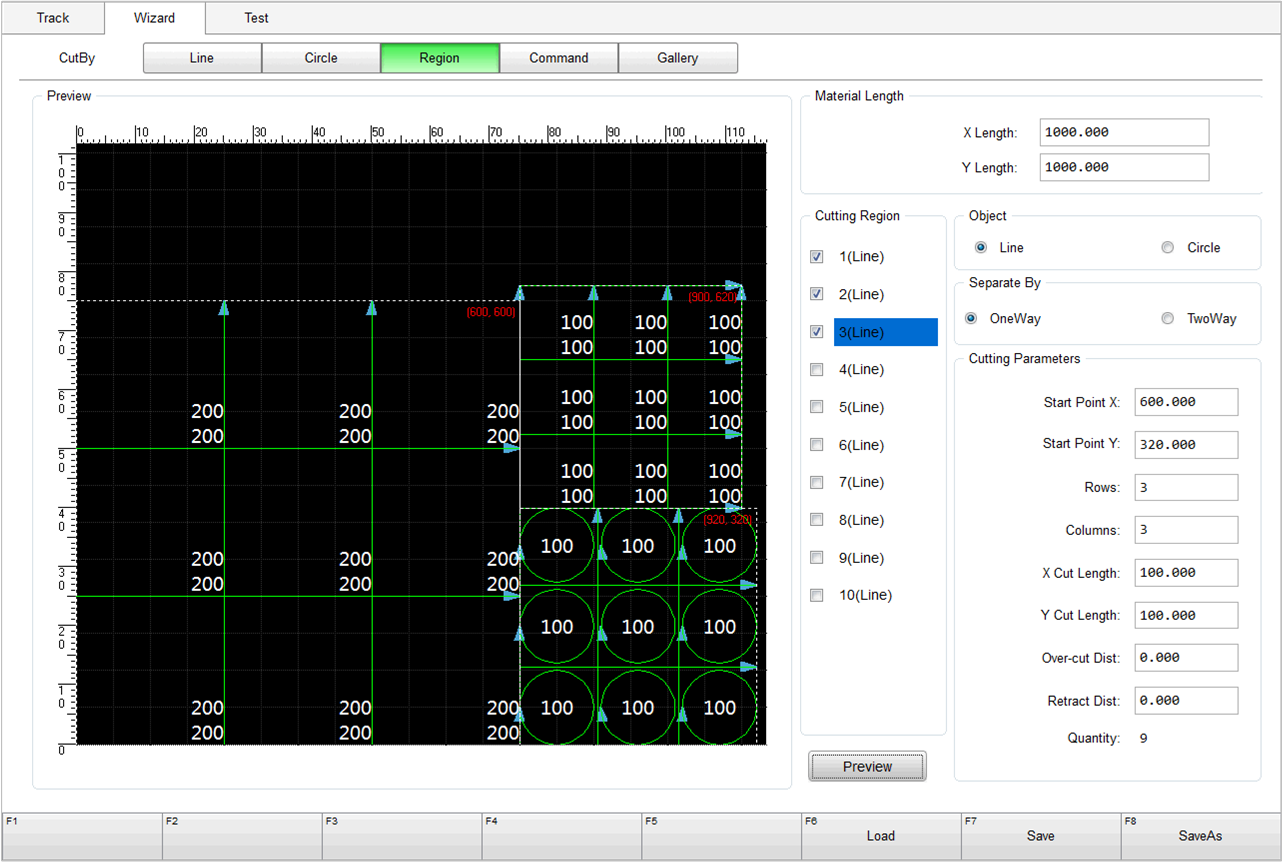
| Parameter | Description |
|---|---|
| Start Point X/Y | Start point of tool cutting. |
| Rows | Set cutting row number. |
| Columns | Set cutting column number. |
| X/Y Cut Length | Cut length in X-axis/Y-axis direction. |
| Over-cut Dist | Cut allowance that exceeds effective distance. Used to decide the end point for tool and avoid damaging glass within effective distance. |
| Retract Dist | Cut allowance ahead effective distance. Used to decide the start point for tool and avoid damaging glass within effective distance. |
Use Command Cut Mode
Command cut mode assists users to generate machining toolpath.
Following commands are supported by NcStudio V10 software:
- Line cut command X, Y, Z, W, Q and R
- Multiplier command M
- Diagonal cutting command A, B, C, D
The following figure is circle cut mode wizard interface:
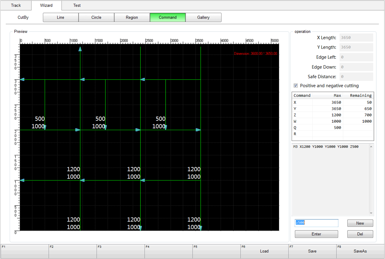
| Parameter | Description |
|---|---|
| X/Y Length | Length of material in X-axis/Y-axis direction. |
| Edge Left | Reserved scrap area in the left of material. |
| Edge Down | Reserved scrap area at the bottom of material. |
| Safe Distance | Vertical distance between tool head and glass. Used to protect tool from plunging and collision during cutting. |
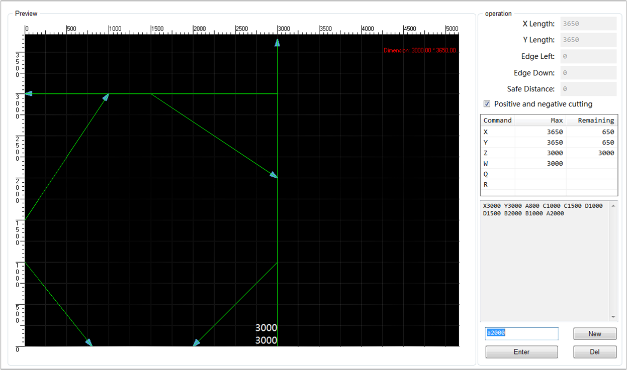
Description of commands:
X cut command:cut from the bottom edge of the material to the top edge vertically. Measure from the origin edge or last X cut line.

Y cut command:Cut lengthways. Measure from the origin edge and the first X cut line, or between two X cut lines.
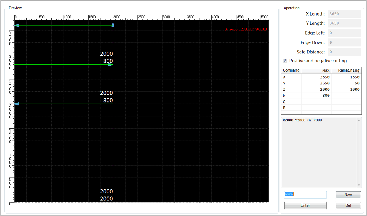
Z cut command:cut vertically. Measure from the bottom edge and the first tool Y cut line of second material, or between two Y cut lines.

W command:cut lengthways. Measure from the origin edge and the first tool W line cut, or between two W cut lines.
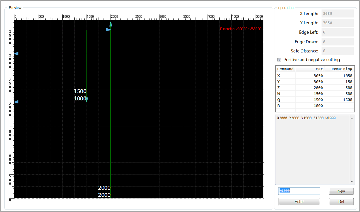
Q command:cut vertically. Measure from the origin edge and the first tool W line cut, or between two W cut lines.
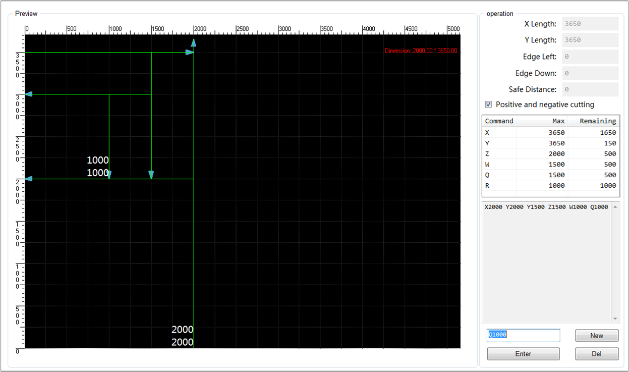
R command:cut horizontally. Measure from the origin edge and first tool Q cut line, or between two Q cut lines.

Multiplier command M:if you use multiplier before command X, Y, Z, W, Q, R, the other cut commands will be executed repeatedly.
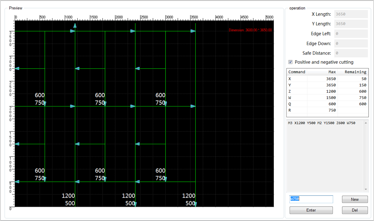
Diagonal cutting command:diagonal cutting command A, B, C, D should be used in pair. Each command corresponds to an edge of fragment area. To diagonal cutting command A and D, the start point is on the left. While to diagonal cutting command B and C, the start point is at the bottom.
Use Gallery
Gallery function supports setting parameters for graphics, generating machining toolpath file and loading to machine it.
The following figure is circle cut mode wizard interface:

To know more about X/Y Length, Margin Tolerance, X/Y Margin, ColSpace and Row Space, please refer to Use Line Cut Mode or Use Circle Cut Mode.
| Parameter | Description |
|---|---|
| X/Y No Separate | No split line between each two lines in X/Y direction. |
| X/Y Sep By One | One split line between each two lines in X/Y direction. |
| X/Y Sep By Two | One split line every two lines in X/Y direction. |
Use Label
Label function supports labeling on each piece of glass.
Before labeling, check whether the printer has been installed and commissioned:
If the printer has been installed, confirm the following:
The machine has been connected with printer (with ethernet port).
The printer works well.
The printer can be controlled through third party BarTender.exe and PrintLabel.exe.
If the printer has not been installed, please refer to Commissioning of NcStudio V10 Glass Cutting Label.
To use label function, do the following:
Click Parameter. Parameter dialog box pops up.
In the dialog box, click Technics to switch to Technics interface.
Click Manufacturer in the dialog box.
Set the following parameters according to actual situation:
- N84061 Printer Position
- N84062~N84063 Labels Placement Position
- N84072~N84073 Labeler-Cutter-Head Offset
- N84083 Labeling Position
Set the value of N84060 Enable Labeling as Yes.
Optional: Set other parameters according to actual situation.
The following figure shows label parameters:

Click Load to load a file with label information.
Click
. Labeling starts.
Continuously Machine
For batch operation, continuous machining is a good choice.
To machine continuously, do the following:
Click Continuous in tool bar. A dialog box named Continuous Processing pops up:

Select Naming rule in the dialog box.
The system provides four naming rules.
If the file name is one of them, the system records and displays its related information.
If the file name is not one of them, click Edit to set its machining parameters information.
Click Add. Select the file.
Double click Process Times value. A dialog box pops up. Fill in the information according to actual situation.
Click Load.
Select Streamline/EdgeFindOnly/DirectCut.
Click Parameter. A dialog box pops up.
Click Overview and Manufacturer. Set the following parameters:
EdgeFindOnly/DirectCut:
- N84012 Edge Finder Position Box Delay
- N84045 Enable Position Box
Streamline:
- N84000 Up Cylinder Delay
- N84012 Edge Finder Position Box Delay
- N84045 Enable Position Box
- N84050 X
- N84051 Y
Click
to start machining.Click input port Ejection.
In online status, the system will transfer and load the glass that has been cut, and automatically machine the next toolpath.
Set Absolute Value
The servo system of absolute encoder supports recording machine origin position. Through this function, set machine origin once during commissioning. When it is used in practice, returning to machine origin is not required.
To use absolute function, a servo motor with absolute encoder is required.
To set absolute value, do the following:
Click Machine Tool. A dialog box pops up.
Set datum.
If If the datum has been set before, do the following:
Click OneCorrect.
Click DoubleJIGGLE. A dialog box named DoubleJIGGLE pops up.
Click Y BK.REF.PT.
If the datum has not been set before, do the following:
Click OneCorrect.
Click DoubleJIGGLE. A dialog box named DoubleJIGGLE pops up.
Adjust axis according to actual position of Y1Y2 axes.
Click OK.
Compare the verticality between X-axis and Y-axis and the parallelism between Y1-axis and Y2-axis. If it does not meet the requirement, set datum again.
Move the target axis to machine origin.
Click RefSet.
Password is required.Click the datum button that corresponds to the axis.
Click OneCorrect.
Close the dialog box. Restart the software.
After the software is updated, the datum information will be lost. Restore the software via Import Datum and Export Datum.