Quick Start
This part introduces NcStudio V10 glass cutting system machining process.
The machining process includes the following:
- Commission before returning to origin.
- Return to machine origin.
- Detect I/O port.
- Set speed and eccentricity.
- Import machining file.
- Set workpiece origin.
- Execute simulation and analog.
- Execute auto machining.
Commission Before Returning to Origin
To commission before returning to origin, do the following:
Adjust Pulse Equivalent
The smaller pulse equivalent is, the higher the machining accuracy and surface quality will be. While the larger, the faster feedrate will be.
Therefore, lower pulse equivalent should be set under the condition of meeting the demand of feedrate.
To adjust pulse equivalent, do the following:
Click Parameter. A dialog box named Parameter pops up.
On Machine interface, click Manufacturer. Double click parameters N10010~10013 Axis Pulse Factor. An input box pops up.
Enter the value of each parameter in the input box.
Click F1 OK.
The adjustment takes effect after the system is restarted.
Check Axis Direction of Machine
Checking axis direction of machine is required before homing.
Before checking axis direction of machine, set Pulse equivalent parameter to confirm that the direction of the axis is the same as actual situation.
To check axis direction of machine, do the following:
Click Parameter. A dialog box named Parameter pops up.
On Machine interface, click Manufacturer. View the values of parameters N10000~10003 Axis Direction.
In machine control area, click
 to switch to Manual mode.
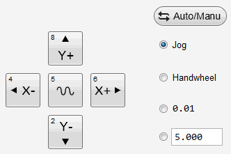
To control the machine moves in the direction of the selected axis, do one of the following:
Select Jog mode:
Select the axis direction in machine control area or on the keypad.
If you press the direction button, the machine will move in the direction at jog feedrate until you release the button.
If you click the direction key
 /
/ /
/ /
/ and
and  at the same time, the machine will move at rapid jog feedrate.
Select Handwheel mode:
Decide axis direction and override on the handwheel, and rotate it. The machine will move in the direction.
Select step length 0.01 mode or custom step length mode:
Click the direction key. The machine will move the step length in the direction.
Check if the actual direction of axis is the same as the set direction of parameters N10000~10003 Axis direction parameter:
- Same: The axis direction is correct.
- Opposite: Set the value of parameter N10000~10003 Axis direction to the opposite value.
Set Workbench Stroke
To use soft limit function in NcStudio V10, please set workbench stroke according to actual size of the machine.
To set workbench stroke, do the following:
Click Parameter. A dialog box named Parameter pops up.
On Machine interface, click Manufacturer.
Double click parameters N10020~10023 Workbench Lower Limit and N10030~10033 Workbench Upper Limit.
Enter the value of each parameter according to actual size of the machine.
Click F1 OK.
The setting takes effect after the system is restarted.
Note: If it is your first time to set the upper and lower limits of the workbench stroke, confirm the effective machining range of the machine.
Return to Machine Origin
To confirm the machining position is correct, please execute returning to machine origin.
The following functions can be used after executing returning to machine origin:
- Enable soft limit
- Set fixed point
- Tool change
To execute returning to machine origin, do the following:
Click
 , a dialog box named BKRef pops up.
In the dialog box, do one of the following according to actual situation:
Click All Axis.
If it is X1X2 or Y1Y2 configuration, click Detect Y. REF before clicking All Axis.
Click Set Directly.
Set current position as machine origin.
Click X-axis/Y-axis/A-axis.
After returning to machine origin,
 appears on operation panel.
Detect I/O Port
Polarity of I/O port is determined by the type of the switch. For a normally closed switch, the polarity is N(Normally closed) by default; for a normally open switch, the polarity is P(Normally open) by default.
To detect I/O port, do the following:
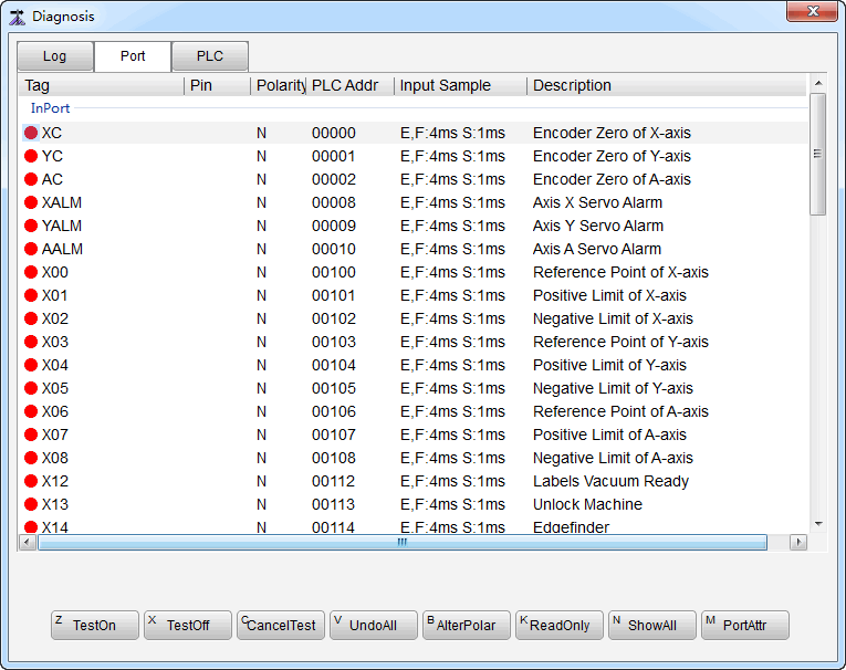
Click Port. A dialog box named Diagnosis pops up:

Current status of each I/O port diaplays in the dialog box. It is helpful for monitoring and troubleshooting.
Select the target port, and click Alter Polar. A dialog box named NcStudio pops up.
Click OK to restart the software. Modification takes effect.
Select the target Input port, and click Port Attribute. A dialog box named Port Attributes pops up.
Set Sampling Interval, check Filter and Port Enable and modify Port Name and Port Desc in the dialog box.
Click OK.
Note: If the port polarity is wrong, modify it; otherwise, alarm prompt or other failure will occur.
Set Speed and Eccentricity
Setting speed parameters and eccentricity parameters are required before machining.
Set Speed Parameters
During auto machining, adjust current feed override to control feed speed.
Calculation formula:
Actual value of feed speed = Current feed override * Set value of feed speed
To set speed parameters, do one of the following:
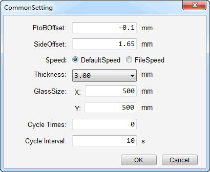
Click Setting. A dialog box name Common Setting pops up:

Select Speed according to actual situation.
Click Parameter. A dialog box named Parameter pops up.
Under Machine interface, click Manufacturer. Double click parameter N72001 SPEED ASSIGN TYPE. Enter the value in the input box. Click F1 OK.
Please refer to Set Parameters for details.
Set Eccentricity Parameters
There exists relative offset distance between cutting tool (work point) and control point. To solve this problem, the distance is shown as fore-and-aft eccentricity parameter, and the system compensates toolpath automatically via eccentricity value.
Side eccentricity refers to X-axis offset of the tool. Fore-and-aft eccentricity refers to Y-axis offset of the tool.
Before setting eccentricity parameters, measurement is required. See following figures for eight kinds of eccentricities:
No fore-and-aft eccentricity

No side eccentricity

Both fore-and-aft eccentricity and side eccentricity exist


To set eccentricity parameters, do the following:
Click Window → NcEditor to switch to NcEditor. Draw the following graphic:

Click File → Save to save the graphic.
In NcStudio, click
 .
.The graphic and the machining track will be displayed in Track window.
Drag the ruler on the left and above sides of Track window. Decide eccentricity according to the ruler.
Click Setting. A dialog box named Common Setting pops up.
Enter eccentricity values in the dialog box.
Click OK.
Import Machining File
To import machining file, do one of the following:
Load Machining File in NcStudio
To load a machining file in NcStudio, do the following:
To find the machining file, do one of the following:
- Click File → Open and Load in menu bar.
- Click Load in the toolbar.
Select and Open the target file.
Optional: Convert the file into a NCE file by setting parameter N65000.
Import Machining File in NcEditor
To import a machining file in NcEditor, do the following:
Click File → Import G Code File.
Select and Open the target file.
Optional: The importing file will cover the original one. To save the original one, click Edit → Insert G Code File.
Draw Machining Object in NcEditor
To draw a machining object in NcEditor, do the following:
To select drawing tools, do one of the following:
- In menu bar, click Draw. Select drawing tools in the pull-down list.
- In drawing toolbar, click drawing tools.
Draw the machining object.
Click File → Save to save the graphic.
The file is saved as a NCE file which will be loaded in NcStudio automatically.
Set Workpiece Origin
Setting workpiece origin is required before machining.
To set workpiece origin, do one of the following:
Set Workpiece Origin in NcStudio
To set workpiece origin in NcStudio, do the following:
Move each axis of the machine to the target position.
Click
 to reset the coordinate of current position.
The current position will be the workpiece origin during machining.
Set Workpiece Origin in NcEditor
To set workpiece origin in NcEditor, do the following:
To open Set Origin dialog box, do one of the following:
- In menu bar, click Draw → Set Origin.
- In toolbar, click
 .
.
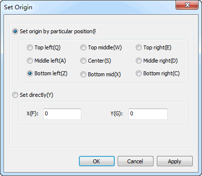
A dialog box named Set Origin pops up:

Set in the dialog box as actual situation.
Click OK.
Execute Simulation and Analog
After setting workpiece origin, to learn the motion forms of machine in advance to prevent the damage of machine caused by programming errors, execute simulation or analog.
Execute Simulation
In simulation process, the system only shows the machining path of tools in Track window and does not drive the machine to take any machining actions.
To execute simulation, do the following:
Click Operate → Simulation Mode in the menu bar.
Click
 . Simulation starts automatically.
Click Operate → Stop Simulation and withdraw the simulation Mode to stop simulation.
Execute Analog
In analog process, the system will drive the tool to simulate toolpath on the XY two-dimensional surface in a safe height without opening the air cylinder and driving Z-axis.
To execute analog, do the following:
Click
 to switch to Auto mode.
Click
 .
.Click
 .
.
In analog process, the air cylinder does not descend, so the glass will not be cut. There are also no port outputs. The machining time in analog is the same as that in normal machining.
Execute Auto Machining
Auto machining process including four parts:
Start Auto Machining
To start auto machining, do one of the following:
- Click F9 on the keyboard.
- Click
 .
. - Click Operate → Start in menu bar.
Pause Auto Machining
To pause auto machining, do one of the following:
- Click F10 on the keyboard.
- Click
 .
. - Click Operate → Pause in menu bar.
Stop Auto Machining
To stop auto machining, do one of the following:
- Click F11 on the keyboard.
- Click
 .
. - Click Operate → Stop in menu bar.
Use Breakpoint Resume
Prerequisites:
- In emergency situation, like power interruption, E-stop, etc.
- The workpiece coordinate is correct.
Step:
- Click Shift+F9 on the keyboard.
- Click Operate → Breakpoint Resume in menu bar.