Auxiliary Drawing Operations in NcEditor
This chapter mainly focuses on auxiliary drawing operations, including:
- Setting lead line
- Catch option
- Combining objects
- Group
- Array
- Chamfer
- Setting tool path
- Expanding bidirectionally
Set Lead Line
If the object is closed, set lead line in workpiece scrap area of toolpath to avoid machining error and workpiece damage.
To set lead line, do the following:
Select the target closed graphic.
Do one of the following to call Set Introduce dialog box:
- Right click in edit window and select Set Introduce.
- Click Object → Set Introduce in menu bar.
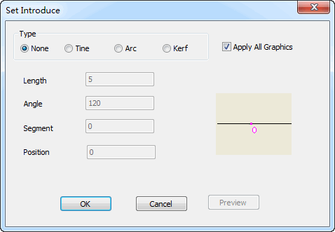
Set Introduce dialog box is as follows:

Select lead line type and enter values of related parameters in the dialog box.
Click OK.
Catch Option
Catch option is used to catch feature points of object in drawing precisely.
To use catch option function, do the following:
Do one of the following to open Catch Option dialog box:
- In menu bar, click View → Catch Option.
- In tool bar, click
 .
.
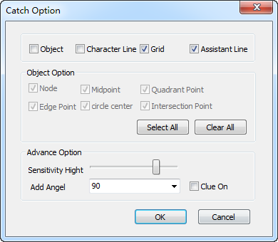
Catch Option dialog box is as follows:

Check the feature points that you need to catch according to the shape of the graphic.
Set Sensitivity Hight and Add Angel.
Click OK.
Combine Objects
This function is used to combine straight line, arc and open polyline mutually, and improve machining efficiency.
To combine objects, do the following:
Click Object → Combine Object Tolerance Setting. A dialog box named Combine tolerance setting pops up:

Enter Tolerance value according to actual situation.
Click OK.
Select at least two objects whose endpoints are near to each other.
Do one of the following to combine the selected objects:
- Click Object → Combine Object in menu bar.
- Right click in edit window and select Combine Object.
Use Group
Group function includes the following:
Group
Group function is used to edit objects integrally.
To use group function, do the following:
Do one of the following to select target objects:
- Check the objects in object list area.
- Press Ctrl in keyboard and click the objects at the same time.
Do one of the following to compose the objects:
- Click Object → Group in menu bar.
- Right click in edit window and select Group.
Disband Group
Disbanding group function is used to edit part of objects.
To disband group, do the following:
Check the target group in object list area.
Do one of the following to disband the group:
- Click Object → Break Group in menu bar.
- Right click in edit window and select Break Group.
After disbanding, the objects in this group will return to last group.
Use Array
To improve machining efficiency, use array function to display objects in rectangular or circular array during batch machining.
To use array function, do the following:
Select an object or group in object list area.
To array multiple objects or groups, group first.
Click Object in menu bar or right click, and select array type:
- Rect array
- Circle array
A dialog box pops up.
Set parameters in the dialog box.
Click OK.
The selected objects will be dispayed in rectangular or circular array.
Use Chamfer
To deburr on parts, use chamfer function to cut the angle of workpiece to slope.
To use chamfer function, do the following:
To call Chamfer Parameter Setting dialog box, do one of the following:
- Click Object → Champfer in menu bar.
- Right click in edit window and select Champfer.
Chamfer Parameter Setting dialog box is as follows:

Select chamfer type, mode and size setting mode, and enter size.
Select Distance mode: Enter chamfer distance between two edges.
Select Angle mode: Enter chamfer length and angle of the first edge.
Click OK.
Click the object.
Set Tool Path
Tool path function is used to set tool compensation by setting tool diameter.
To set tool path, do the following:
Check the target object to select it in object list area.
To call Tool path, do one of the following:
- Click Object → Tool Path in menu bar.
- Right click in edit window and select Tool Path.
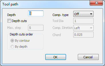
Tool Path dialog box is as follows:

Enter the values in the dialog box.
Click OK.
Expand Bidirectionally
Expanding bidirectionally function is used to set left and right tool compensation at the same time.
To expand bidirectionally, do the following:
Check the target object to select it in object list area.
Do one of the following to open Gap compensation dialog box:
- Click Object → Expand Bidirectionally in menu bar.
- Right click in edit window and select Expand Bidirectionally.
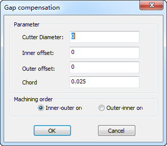
Gap compensation dialog box is as follows:

Enter the values in the dialog box.
Click OK.