Software Overview
Through this section, you can quick know the hardware and software of NcStudio V10 Waterjet Cutting CNC System.
Hardware
Host
Lambda terminal board
EX series extended terminal board: EX31A
Software
NcStudio V10 Waterjet Cutting CNC System includes multiple softwares with different axes (General Five-axis AB, General Five-axis AC). This manual takes NcStudio V10 General Five-axis AC (Bus) as an example to introduce how to use this system.
About the software interface of NcStudio V10 Waterjet Cutting CNC System, see Software Interface.
Host
You can choose one of the following for host control:
NC65C Industrial Personal Computer
NC65C industrial personal computer, also called NC65C Controller (hereinafter referred to as NC65C).
The structure and interface definition of NC65C are as follows:
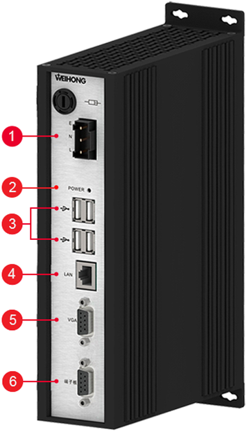
Interface of LNE (live wire, neutral wire and earth wire)
It is used to connect to a 220V power supply.
Indicator light
It is an indicator light for the power supply.
USB 2.0 interface
It is used to transmit data with a USB flash disk.
LAN interface
Its transmission rate is 100 Mbps.
VGA interface for a display screen
It is used to connect to a display screen.
Interface for a Lambda terminal board
It is used to connect to a Lambda terminal board.
PM95A Control Card
When PM95A control card is used with NcStudio, you need to insert it into PCI-E slot of your computer.
PM95A is shown as follows:

Lambda Terminal Boards
This system supports the following Lambda terminal boards:
Lambda 5M
It is used for the bus control system.
Its structure and interface definition are as follows:

Indicator light
Power: An indicator light for the power supply
System: An indicator light for the system
24V power interface
It has anti-reverse connection protection.
Interface for switching high-low level
It is used to switch between the high level and low one.
General input ports
They include X00 ~ X27.
Interface for extended terminal board
A high-speed 485 interface. It is used for cascade and adopts serial communication. The baud rate is 10Mbps.
General output ports
They include Y00 ~ Y07 and 5 general ports.
Analog output port
Analog voltage: 0 ~ 10V
Precision: 0.2V
Handwheel interface
It is used to connect to a handwheel (supporting the 6-axis handwheel at most).
M-II bus interface
It is used to connect to a M-II bus drive. And the interpolation period of pulses is 1ms.
Moving-axis interface
It is used to connect to a servo drive.
Host interface
It is used to connect to NC65C, NC60A, etc.
Lambda 5E
It is used for the non-bus control system.
Its structure and interface definition are as follows:

Interface for a 24V power supply
It has anti-reverse connection protection.
Interface for switching high-low level
It is used to switch between the high level and low one.
General input ports
They include X00 ~ X27.
Interface for extended terminal board
A high-speed 485 interface. It is used for cascade and adopts serial communication. The baud rate is 10Mbps.
General Output ports
They include Y00 ~ Y07 and 5 general ports.
Analog output port
Analog voltage: 0V ~ 10V
Precision: 0.2V
Handwheel interface
It is used to connect to a handwheel (supporting the 6-axis handwheel at most).
Moving-axis interface
It is used to connect to a servo drive.
Host interface
It is used to connect to NC65C, PM95A, the integrated CNC system, etc.
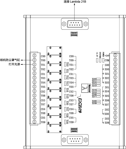
Lambda 21B
It is used for the bus control system.
Its structure and interface definition are as follows:

General input ports
They include X00 ~ X37.
Extended interface
A DB9 interface. And it is called EXT.
Handwheel interface
It is called MPG.
General output ports
They include C00 ~ C17 / Y00 ~ Y17.
Output interface for analog voltages
- AVC: An output interface for analog voltages
- GND: The ground for analogy voltages
Configurable ports for I/O valid level
NPN / PNP is configurable (S -> 24V / S -> com):
- S1: Configure the valid level of X00 ~ X27.
- S2: Configure the valid level of X28 ~ X37.
Ground interface
It is used to connect to the ground.
Power supply interfaces
+24V: Positive input for 24V DC
COM: The ground for 24 DC
Mechatrolink-II communication interface
A RJ45 interface. And it is called LINK. The axis quantity is at most 16.
Pulse-axis communication interface
A DB15 interface. And it is called AXIS. It supports an incremental encoder.
Host communication interface
A DB6 interface. And it is called HOST. It follows the Phoenix bus protocol.
EX31A
EX31A, the extended board of the Lambda terminal board, adopts the mounting structure of module rack, for good protection and easy installation.
Its structure and interface definition are as follows:
Power supply input
24V / 0.5A input (+24V, COM).
Input ports
It supports a 10-path input and NPN / PNP can be configurable (S -> 24V / S -> COM)
S ports include the following:
- S0: X00 ~ X03
- S1: X04 ~ X07
- S2: X08
- S3: X09
Communication interface
It is used for the cascade port communication and follows the Phoenix bus protocol.
Output ports
They support the 10-path relay contact output.
Communication interface
Uplink port communication. It follows Phoenix bus protocol.
Software interface
NcStudio V10 Waterjet Cutting CNC System has the following interfaces:
NcStudio Interface
The main interface of NcStudio is as follows:
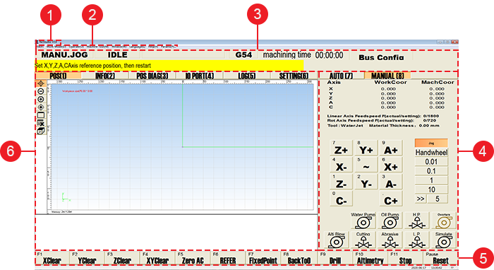
Menu Bar
It includes the following menus:
File: It is used to load / unload program files, generate an installation package, restart / shut down the system, etc.
Work Mode: It is used to switch among Auto mode and Manual modes (including jog, handwheel and step modes).
Operate: It is used to execute machining commands, such as executing single block, setting the workpiece origin, executing simulation, rotating / mirroring toolpath, etc.
Machine Tool: It is used to execute operations related to machine tools, such as customizing valve ON / OFF order, checking time statistics for high pressure valve and oil pump, managing wearing parts, etc.
Window: It is used to switch among track, machining information, position diagnosis, hardware port, log and setup interfaces, show or hide NcEditor interface, open PLC or Manual Code dialog box, etc.
Language: It is used to switch a system language.
Help: It is used to check the system information, register the software, set the setup interface, open NcGateway interface, use the velocity calculator, etc.
Params: It is used to check and set common parameters about waterjet cutting.
CNC Status Bar
It includes the following:
Current operation mode: Auto, manual, etc.
Current system status: Running, idle, E-stop, etc.
Current running status: Normal running, normal or abnormal stop, etc.
Current workpiece coordinate system (WCS): G54 ~ G59
Machining time
Current system configuration: Bus type, standard A type and double-Y A type.
System prompts, alarms, etc.
Machine Tool Control Bar
It includes the following:
Axis coordinate area: It shows the current machine coordinate and workpiece coordinate of each axis:
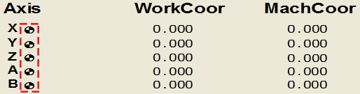
After returning to the machine origin, the sign
 appears after each axis.
Feed speed area: It shows the actual feedrate and set value of linear axes and rotary axes.
Tool area: It shows the current tool and material thickness.
File area: It shows the name of current program file.
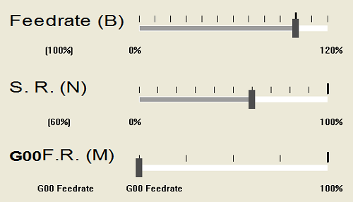
Operation mode area: The display differs in the operation mode:
Auto mode: It is used to adjust feedrate, abrasive valve and G00 rate during automatic machining:
Manual mode:
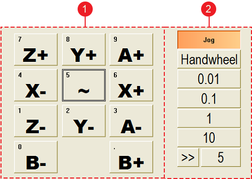
Axis direction buttons: It is used to move each axis towards positive / negative direction.
Note: Please do not click an axis direction button too frequently because the system needs a certain time to execute the command.
Mode buttons: It is used to switch among the following modes:
Jog: Click Jog and do one of the following:
Click an axis direction button. The machine tool keeps running until you release the button.
Click several axis direction buttons. The clicked axes move at the same time at jog speed until you release buttons.
This operation is mainly used to move X-axis and Y-axis at the same time.
Click
 and an axis direction button. The machine tool moves at rapid jog speed.
Handwheel: Click Handwheel, select the axis direction and handwheel override and rotate the handwheel for a certain degrees. The machine tool is controlled by the handwheel and moves towards the selected direction.
Step: Select a step size among 0.01, 0.1, 1,10 or click
 to customize the step size (default value: 5mm), click an axis direction button and then release it. The machine tool moves the selected step size.
Note: The step size should not be too large, otherwise, the machine tool may be damaged due to misoperations.
Port control area: It is used to turn on / off the following common ports:
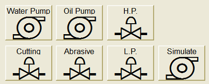
Note: The rotating workbench is used to load / unload relatively large or heavy sheets by its rotation.
Operational Button bar
Operational buttons differ in the operation mode. They are used to execute related operations.
Function Windows
They include the following windows:
POS: It is used to show the following:
Toolpath in real-time during machining or simulation.
Contents of the program file in Auto mode.
INFO: It is used to show machining records, calculate the machining cost, etc.
POS DIAG: It is used to show feedback coordinates, sent pulse and feedback pulse and set the datum for each axis.
IO PORT: It is used to show the status of each IO port and communication status between the software and hardware.
LOG: It is used to show different types of logs that can help troubleshoot.
SETTING: It is used to set cutting parameters in Auto or Manual mode.
NcEditor Interface
The main interface of NcEditor is as follows:
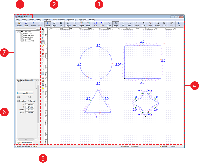
Title Bar
It is used to show the name of current program file.
Menu Bar
It includes the following menus:
File: It is used to create / open / import / save a program file, generate an installation package, restart / shut down the software, etc.
Edit: It is used to undo / redo the operation, select all objects, insert a file, etc.
View: It is used to customize the displayed information in the main interface, adjust the view, return to NcStudio interface, etc.
Draw: It is used to select the object shape, measure distance, set the workpiece origin, lock the view, etc.
Object: It is used to set machining technics, such as chamfer, array, micro joint, bridge, etc.
Work Mode: It is used to switch between Auto mode and Manual modes (including jog, handwheel and step modes).
Operate: It is used to execute machining commands, such as executing single block, setting the workpiece origin, executing simulation and so on.
Language: It is used to switch a system language.
Help: It is used to check the system information, register the software and set the setup interface.
Tool Bar
It includes the following:
 : It is used to open a program file.
 : It is used to save a program file.
 : It is used to cancel the last operation.
 : It is used to recover canceled operations.
 : It is used to translate the view.
 : It is used to zoom in / out the view.
 : It is used to make the view fit to the drawing window.
 : It is used to set the machining direction as clockwise for the target object.
 : It is used to set the machining direction as counterclockwise for the target object.
 : It is used to set the groove direction on the left of the machining direction for unclosed objects.
 : It is used to set the groove direction on the right of the machining direction for unclosed objects.
 : It is used to change the filling attribute for closed objects.
 : It is used to automatically set the filling attribute for closed objects.
 : It is used to delete the lead line.
 : It is used to delete the set tool compensation.
 : It is used to set the mode of vertical plunge, tilt angle and cutting speed.
Drawing Area
It is used to draw the machined objects.
Drawing Auxiliary Bar
It includes the following:
 : It is used to select the object.
 : It is used to set the machining order.
 : It is used to show the machining order.
 : It is used to show the groove direction.
 : It is used to clear the machining track.
 : It is used to set catch options.
 : It is used to disable catching function.
 : It is used to draw a dot.
 : It is used to draw a line.
 : It is used to draw an arc.
 : It is used to draw a polyline.
 : It is used to draw a rectangle.
 : It is used to draw a circle.
 : It is used to draw an ellipse.
 : It is used to draw a polygon.
 : It is used to draw a start.
 : It is used to add text.
Object Attribute Area
It is used to set the following attributes for the selected object:
For one object
- X-axis and Y-axis coordinates
- Width and height / diameter
For all objects
- Width
- Height
- Rotating angle
Object List Window
It used to show all objects in the drawing area according to the drawing order.