Measure Height with the Laser Sensor
Height measurement with the laser sensor is a type of non-contact height measurement conducted before cutting. Currently, three height measurement methods are supported: manual height measurement, three-point height measurement, and scanning height measurement.
Compared with cylinder height measurement that requires contact, it can greatly improve measuring precision and avoid possible damage to the workpiece by keeping the same distance between the tool head and the workpiece surface. It is a perfect choice for rock workpieces with curved or irregular-shaped surfaces, but not applicable to materials with large light transmittance or reflection, such as glass or mirror.
The height measurement mechanism mainly includes the laser sensor, measuring cylinder, protective device, and blowing device.
Note: Waterjet cutting environment normally contains a high level of sand and moisture; therefore, the whole measuring mechanism needs to be dust-proof and water-proof.
Laser Sensor
Ensure that the laser sensor has not run out of its lifespan before using it.
Waterjet cutting environment normally contains a high level of sand and moisture. Therefore, the height measurement mechanism needs to be dust-proof and splash-proof.
Currently, two types of movement laser sensors are supported by WEIHONG systems:
WH-D108-S-J
WH-D33-85
Installation
To ensure better measuring effect, the requirements for installing the laser sensor are as follows:
It is recommended that you make the laser sensor light emitting and reception ports at the same height, which means to keep the laser sensor lower surface horizontal with the machine XY plane as shown below:
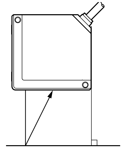
To avoid that the laser sensor is damaged during height measurement, after the measuring cylinder is pushed out in position, the lower surface of the laser sensor should be 10 mm–65 mm higher than the sand tube and 75 mm above the workpiece surface.
Note: The baseline distance between the laser sensor and the workpiece surface is about 85 mm during height measurement.
After installing the laser sensor to the measuring cylinder, ensure that:
During height measurement, the measuring cylinder can be normally pushed out.
After height measurement, the measuring cylinder can be normally pulled in.
After the measuring cylinder is pulled in, the tool head will not collide with the laser sensor during rotating.
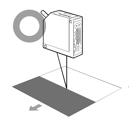
After the laser sensor is installed, its moving direction relative to the workpiece is as follows:
Communication Method
The upper computer normally has a USB or RS232 serial port as the communication port. The laser sensor supports communication via a RS485/RS422 serial port.
Therefore, you can use one of the following methods to achieve communication between the laser sensor and the upper computer:
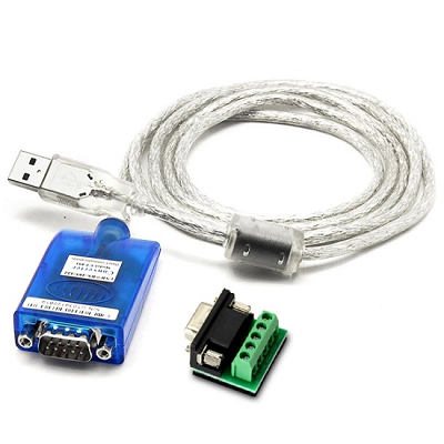
USB to RS485/RS422
Install a USB-to-RS485/RS422 drive on the upper computer. The cables are shown below:
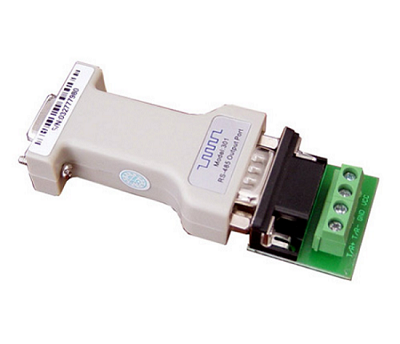
RS232 to RS485/RS422
The upper computer needs to have a RS232 port for connection. The ports are shown below:
Wiring Requirement
The wiring requirements are as follows:
If the laser sensor original cable is 0.5m and requires extension RS485/RS422 communication cables:
- The extension cables need to have a shielding layer and wired separately from other signal cables.
- The extension cable diameter needs to be equal to or larger than that of the laser sensor original cable to avoid signal intervention.
Signal cables for the other functions of the laser sensor need proper anti-short circuit treatment to avoid intervention.
WH-D108-S-J wiring diagram:
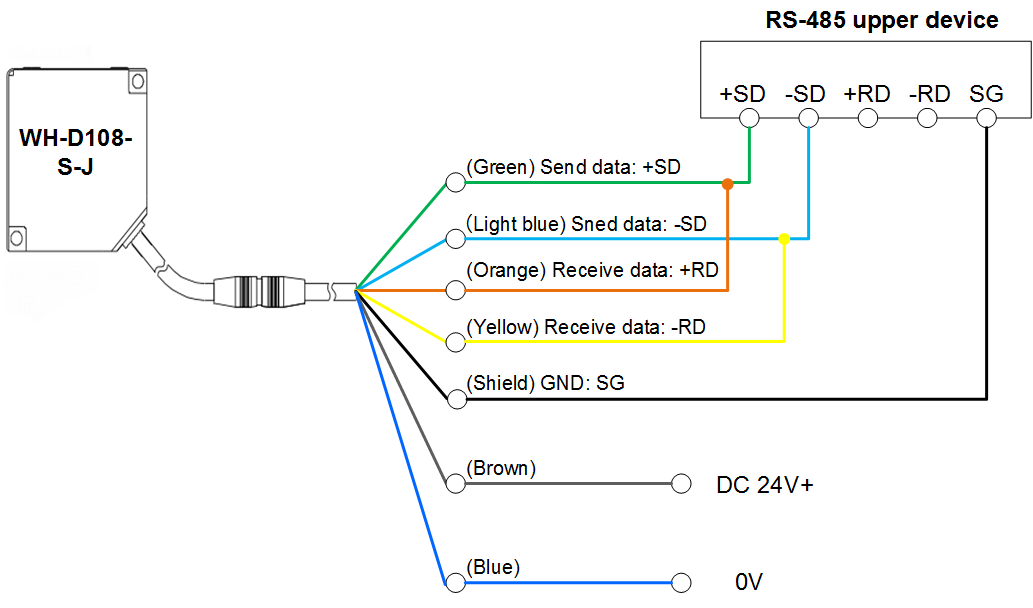
Description:
| Laser Sensor Side | Upper Device Side |
|---|---|
| Green and orange | 485 sending data + (+SD) |
| Light blue and yellow | 485 sending data - (-SD) |
| Shielding cable | 485 grounding (GND) |
| Brown | Power supply +24V |
| Blue | Power supply 0V |
WH-D33-85 wiring diagram:
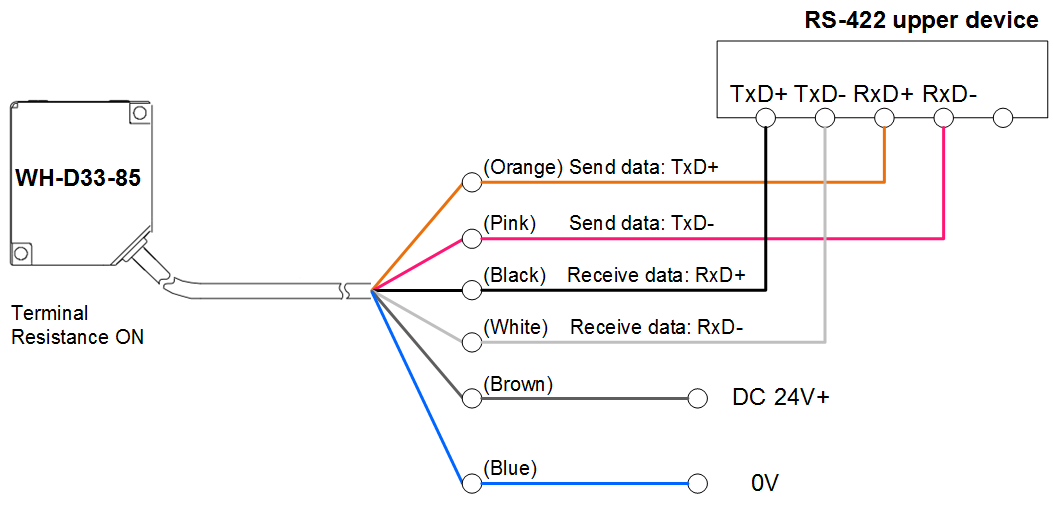
Description:
| Laser Sensor Side | Upper Device Side |
|---|---|
| Black RxD+ | TxD+ |
| White RxD- | TxD- |
| Orange TxD+ | RxD+ |
| Pink TxD- | RxD- |
| Brown | Power supply +24V |
| Blue | Power supply 0V |
Preparation
Before measuring height with the laser sensor, do the following:
Set the Baud Rate of Serial Ports
This operation is used to set the baud rate of serial ports of the upper computer to ensure the communication between the laser sensor and the upper computer.
Prerequisite:
The upper computer is properly connected to the USB-485/422 converter or 232 port.
Follow the steps below to set the baud rate of serial ports:
On the upper computer, go to Computer > Control panel > Device Manager to open the Device Manager window:
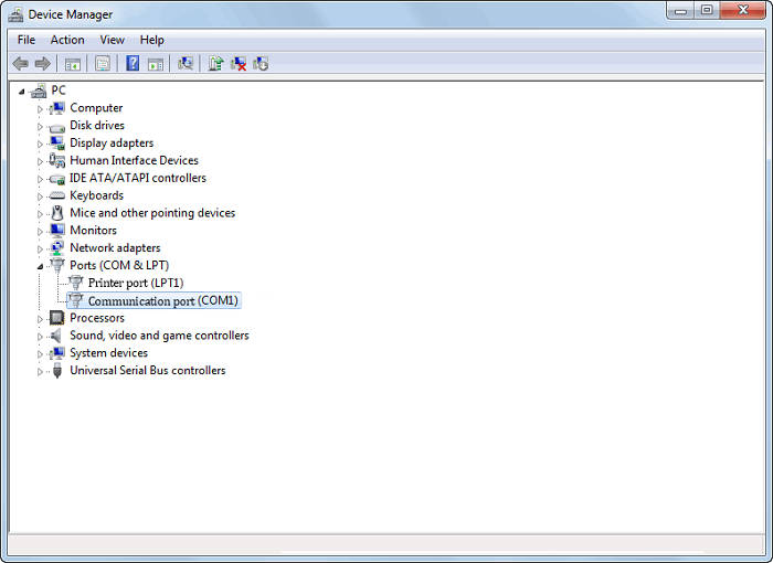
Click Ports (COM & LPT) and double-click the target communication port (such as COM 1) to open the port property window.
Click the Port Settings tab and set Bits per second to 38400.
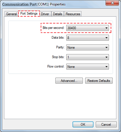
Click OK.
Set the Laser Sensor Model
Set the laser sensor model parameter in the NcStudio software based on the actual situation to ensure connection between the sensor and the software.
Follow the steps below to set the sensor model parameter:
In the menu bar, go to Machine Tool > System Parameters to open the System Parameters dialog box:

Click the following buttons: Params > Other > Manufacturer. Enter the manufacturer password. Set the parameter Types of Laser Sensors.
- 1: WH-D108-S-J
- 2: WH-D33-85
Restart the software to make the setting take effect.
Set the Laser Sensor Port Address
This operation is used to set the port address of the laser sensor into the NcStudio software to ensure communication between the laser sensor and the upper computer.
Follow the steps below to set the port address of the laser sensor:
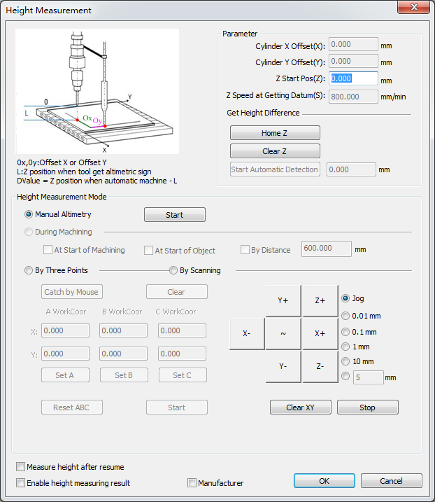
In Manual mode, click the F10 Altimetry operation button to open the Height Measurement window:
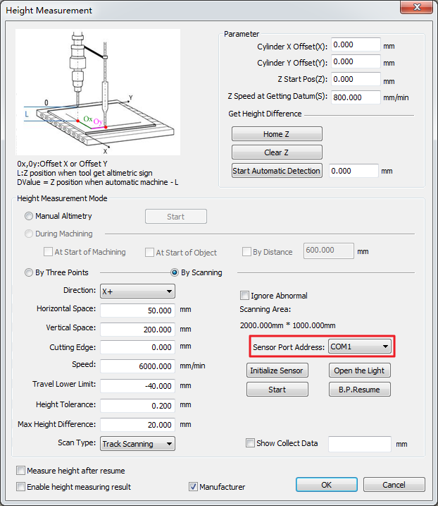
In the window bottom, check Manufacturer. Enter the manufacturer password.
In the Height Measurement Mode region, select By Scanning. Click the Sensor Port Address pull-down menu and select the address, which needs to be consistent with the communication serial port address in the upper computer Device Manager.
For details about setting the port baud rate in the device manager, see Set the Baud Rate of Serial Ports.
Restart the software.
A log will be displayed, indicating that the height measurement serial port has been enabled successfully. This means that the laser sensor communicates with the upper computer normally.
In Manual mode, click the F10 Altimetry operation button to open the Height Measurement window. Click Initialize Sensor.
After a log indicating sensor initialization success is displayed, the initialization is complete.
Follow the steps below to check to see if the sensor port address has been set correctly:
In Manual mode, click the F10 Altimetry operation button to open the Height Measurement window.
In the Height Measurement Mode region, select By Scanning. Click Open the Light/Close the Light and see if the sensor can be controlled to open and close the light correctly.
No: Check the wiring, and communication port and sensor settings.
Set Standard Parameters
Follow the steps below to set the common height measurement parameters:
In Manual mode, click the F10 Altimetry operation button to open the Height Measurement window.
In the window bottom, check Manufacturer. Enter the manufacturer password. Parameters in the Parameter region become available for setting. Descriptions of the parameters are shown below:
Parameter Description Cylinder X Offset(X) The X-axis distance between the laser beam center and the waterjet cutter sand tube center. Cylinder Y Offset(Y) The Y-axis distance between the laser beam center and the waterjet cutter sand tube center. Z Start Pos(Z) The Z axis moves to this position first when the automatic height difference detection or scanning height measurement is started. Z Speed at Getting Datum(S) The Z axis movement speed when the sensor is acquiring the datum position during height measuring. Get Height Difference The difference between height 1 (from the tool head to the workpiece surface during automatic machining) and height 2 (from the tool head to the workpiece surface when height measurement signals are detected). Follow the steps below to set Cylinder X Offset(X) and Cylinder Y Offset(Y):
Move the tool head to a proper position and click Clear XY. Make the tool cut a small hole on the workpiece surface.
Enable the sensor height measuring cylinder to make the sensor pushed out.
Enable the light and move the X and Y axes to make the laser center aligned with the hole center.
Enter the current X and Y workpiece coordinates in the Cylinder X Offset(X) and Cylinder Y Offset(Y) fields respectively.
Set Z Start Pos(Z) based on the actual situation.
Note: When setting the parameters, ensure that:
- The Z axis has gone to the mechanical origin (with the mechanical origin symbol displayed before the Z axis).
- After the sensor is pushed out at the set position, the sensor lower surface is 75 mm-200 mm from the workpiece.
Follow the steps below to acquire the height difference:
Manually move the sand tube to the cutting height and click Clear Z.
Click Start Automatic Detection.
The result will be displayed automatically in the field after the detection is complete.
Note:
- The automatic detection only needs to be executed once. You do not need to clear the Z axis or click Start Automatic Detection again for later machining.
- If the Z axis is cleared again, click Start Automatic Detection again to ensure cutting accuracy and cutter safety.
Height Measurement Operations
The following sections introduce operations for:
Execute Manual Height Measurement
Manual height measurement means to measure the height of a single point. You can complete measurement of material thickness easily in manual height measurement mode without having to clear coordinates manually.
Follow the steps below to execute manual height measurement:
Move the cutter to the target point.
In Manual mode, click the F10 Altimetry operation button to open the Height Measurement window.
In the window bottom, check Manufacturer. Enter the manufacturer password.
In the Height Measurement Mode region, select Manual Altimetry.
Click Start to start height measurement.
After height measurement is complete, click OK.
If any exception occurs during height measurement, such as height measurement device or position exception, or about to collide with the machine, you can click Stop to stop height measurement. If the tool path origin is found out to be wrong, click Clear XY at the correct position and execute height measurement.
Execute Three-Point Height Measurement
Three points in a 3D space can be used to determine a 2D plane.
Three-point height measurement is normally used for workpieces which have flat surfaces but form certain angles with the workbench.
Follow the steps below to execute three-point height measurement.
In Manual mode, click the F10 Altimetry operation button to open the Height Measurement window.
In the window bottom, check Manufacturer. Enter the manufacturer password.
In the Height Measurement Mode region, select By Three Points.
Select one of the following methods to let the system acquire coordinates of three points:
Manually enter the workpiece coordinates of point A, B, and C.
Manually move the X and Y axes to the three target points and click Set A, Set B, and Set C respectively to record the coordinates of the current point for point A, B, and C.
If you want to change the point coordinates, you can click Reset ABC to clear and set the coordinates again.
Click Catch by Mouse and pick three points on the machining path of the POS tab.
If you are not satisfied with the picked points, you can click Clear and select points again.
Click Start to start three-point height measurement.
After three-point height measurement is complete, click OK.
Execute Scanning Height Measurement
Scanning height measurement is a new height measuring method which can generate a scanning track based on the preset workpiece information.
During height measuring, the system automatically acquires the datum value at the scanning start point. The tool head carries the laser sensor during continuous movement and scanning. Accurate height feedback is provided via the laser sensor.
Follow the steps below to execute scanning height measurement:
In Manual mode, click the F10 Altimetry operation button to open the Height Measurement window.
In the window bottom, check Manufacturer. Enter the manufacturer password.
In the Height Measurement Mode region, select By Scanning.
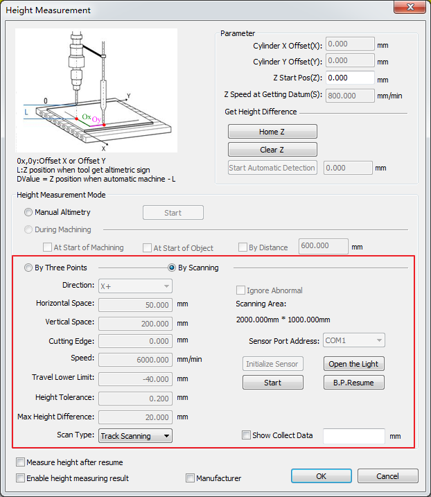
Set Direction to the axis feed direction when scanning is started.
Set Horizontal Space or Vertical Space:
If the scanning direction is X+, set Horizontal Space (the default value is 50 mm).
Increase the Vertical Space value based on the workpiece flatness to improve scanning efficiency.
If the scanning direction is Y+, set Vertical Space (the default value is 200 mm).
Increase the Horizontal Space value based on the workpiece flatness to improve scanning efficiency.
Set the following parameters based on actual situation:
- Cutting Edge
- Speed
- Travel Lower Limit
- Height Tolerance
- Max Height Difference
- Scan Type
- Ignore Abnormal
For details, see Laser Height Measurement Parameters.
If Show Collect Data is checked, real-time data from the sensor will be displayed.
Note: If Show Collect Data is checked, the real-time height measurement data will be displayed in the height measurement window for you to check the communication status and current sensor position.
Click Start. The system generates a scanning track and executes scanning height measurement based on the settings.
After scanning height measurement is complete, check Enable height measuring result and click OK.
If any exception occurs during scanning height measurement, resulting in the system failing to collect continuous data and reporting an alarm indicating "data collection of No.x height measurement point has failed", troubleshoot by referring to Common Problems.
After the problem is solved, select By Scanning in the Height Measurement Mode region and click B.P.Resume to finish the rest of scanning.
Common Problems
This chapter introduces the following common problems during height measuring and provides analysis and solution for your reference:
- Data Collection Failure of a Height Measurement Point
- Communication Error
- Height Measuring Cylinder Failed to Close in Position
- Height Measuring Cylinder Failed to Eject in Position
- Dustcover Ejection in Position Signal Not Detected
- Ensure the Sensor is a Certain Distance from the Material when the Cylinder is Ejected
- Height Measuring Target Position is Lower than the Travel Lower Limit
Data Collection Failure of a Height Measurement Point
Reason:
The Z-axis height tolerance of an adjacent point exceeds the Height Tolerance value and the continuous horizontal distance exceeding the height tolerance exceeds the N93400 Max Ignorable Distance value.
The laser beam goes through the material during height measuring, causing the reading to exceed the detectable range.
The laser beam exceeds the material area or passes a defective area on the material, causing the reading to exceed the detectable range.
Foreign objects are blocking the sensor light emitting or reception side.
The sensor internal structure is damaged due to collision or moisture penetration.
Solution:
Set Height Tolerance to a proper value based on the material surface conditions.
Replace the material or attach a piece of opaque thin film to the material surface.
Readjust height measuring parameter settings so that the laser beam does not exceed the material or pass defective areas. You can also attach a piece of opaque thin film to the defective areas.
Clean the sensor light emitting and reception side.
Suggestion: You can use an air gun to blow foreign objects away. Do not use coarse or hard cloth to rub against the sensor light emitting and reception side.
Replace the sensor.
Communication Error
Solution:
Check to see if the laser sensor type parameter value matches the sensor model currently in use.
If not, reset the parameter Types of Laser Sensors. For details, see Set the Laser Sensor Model.
If a USB-to-RS485/422 converter is used for communication, check to see if the computer drive is installed successfully and re-install the drive if not.
Check to see if the baud rate, data bit, parity bit, stop bit, and other parameters of the computer COM port corresponding to the laser sensor are set correctly and reset the parameters if not.
Check to see if the Sensor Port Address in the Height Measurement window is set correctly and reset it based on the computer COM port if not.
For details, see Set Laser Sensor Port Address.
Check to see if the power supply and communication cable connection of the serial port are normal.
If not, reconnect the cables and turn on the power.
Check to see if the sensor is damaged and replace the sensor if it is.
Height Measuring Cylinder Failed to Close in Position
Explanation:
After height measuring is started, the cylinder is in withdrawn status and the software automatically detects whether there is signal from the height measuring cylinder closing in position port.
Solution:
If the height measuring device is not using the cylinder closing in position signal switch, set the polarity of the Altimetric cylinder withdrew port of the IO PORT tab to P.
Otherwise, check the signal switch position and wiring of the signal cable.
Height Measuring Cylinder Failed to Eject in Position
Explanation:
After height measuring is started, the cylinder is ejected and the software automatically detects whether there is signal from the height measuring cylinder ejection in position port.
Solution:
If the height measuring device is not using the cylinder closing in position signal switch, set the polarity of the Altimetric cylinder ejected port of the IO PORT tab to P.
Otherwise, check the signal switch position and wiring of the signal cable.
Dustcover Ejection in Position Signal Not Detected
Explanation:
Before sensor ejection, the software automatically detects whether the dustcover is ejected in position. If it does not detect the dustcover ejection in position signal during the time, it reports this alarm.
Solution:
If the height measuring device is not using the dustcover in position signal switch, set the polarity of the Dust cover pops up in place port of the IO PORT tab to P.
Otherwise, check the wiring of the dustcover in position signal cable.
Ensure the Sensor is a Certain Distance from the Material when the Cylinder is Ejected
Reason:
The sensor is too close from the material surface when the cylinder is ejected from the height measuring start position.
Solution:
In the Height Measurement window, set Z Start Pos in the Parameter region to a high value as allowed by the Z axis travel limits.
If the Z Start Pos value cannot be increased due to restriction of the Z axis travel limits, it means that the height measuring mechanism does not allow measuring of materials of this width. In this case, you can optimize the height measuring mechanism.
Height Measuring Target Position is Lower than the Travel Lower Limit
Reason:
The height measuring target position is lower than the lower limit set for the laser head. As a result, the sensor cannot move to the target position.
Solution:
Set Travel Lower Limit to a lower position.