Set the Structure of Five-axis Tool Head
Through RTCP algorithm, this operation helps to solve additional motions of the tool head during the rotary axis rotates, resulting from the fact that the control point of the CNC system may be not on the tool head due to the installation. As a result, the CNC system will automatically correct the control point and the tool head will move along the toolpath specified by commands.
At present, both five-axis AB and five-axis AC software support to customize the structure of tool head.
Structures of Tool Head
The description about structures of tool head is as follows:
Main rotary axis: Its rotation can change the position of the other rotary axis.
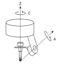
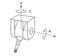
For the AC head tool, the main rotary axis is C-axis; for the AB head tool, it is B-axis.
Auxiliary rotary axis: Its rotation cannot change the position of the other rotary axis.
The auxiliary rotary axis is A-axis.
Control point: The point where the center lines of two auxiliary rotary axes intersect.
Cutting point: The optimal point where the spouted water and workpiece surface intersect.
In general, it is 3mm ~ 5mm below the abrasive tube.
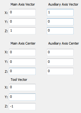
Vector of main rotary axis: The direction vector of the main rotary axis in this coordinate system, taking the cutting point as the origin of space coordinate system.
In general, one of X-axis, Y-axis and Z-axis coordinates is set to 1. E.g. (0,0,1)
Vector of auxiliary rotary axis: The direction vector of the auxiliary rotary axis in this coordinate system, taking the cutting point as the origin of space coordinate system.
In general, one of X-axis, Y-axis and Z-axis coordinates is set to 1. E.g. (1,0,0)
Center of main rotary axis: The coordinate of an arbitrary point on the main rotary axis in this coordinate system, taking the cutting point as the origin of space coordinate system.
Center of auxiliary rotary axis: The coordinate of an arbitrary point on the auxiliary rotary axis in this coordinate system, taking the cutting point as the origin of space coordinate system.
Vector of tool rod: The direction vector of spouted water when each rotary axis rotates to 0°.
Default: (0,0,-1)
Set Five-axis AB Tool Head
To set five-axis AB tool head, do the following:
Click Params. Params dialog box pops up:
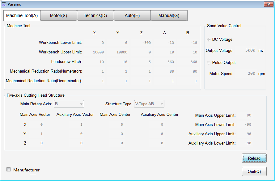
To activate input boxes, check Manufacturer and input the manufacturer password.
Select B-axis as the main rotary axis.
Select Tool head structure and do related operations:
For option 90°AB / 45°AB / V-type AB, set Waterjet tool length in Technics interface.
For option Customize, customize all tool parameters.
About parameter details, see Structures of Tool Head.
To validate parameter settings, reload a program file.
Set Five-axis AC Tool Head
To set five-axis AC tool head, do the following:
Click Machine Tool → Machine Tool. Machine Tool dialog box pops up:
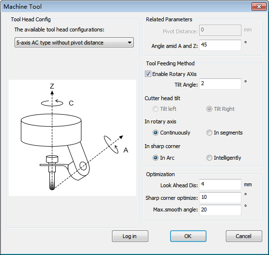
Click Log in, and input the manufacturer password.
Select the structure of tool head and do related operations:
For option 5-axis AC type without pivot distance, set Angle amid A and Z according to the actual situation.
In general, the angle between A-axis and C-axis is 45°.
For option 5-axis AC type with pivot distance, set Y offset of A-axis, X offset of C-axis, Y offset of C-axis and Pivot Distance.
For option 5-axis AC Custom Tool Head, customize all tool parameters:
About parameter details, see Structures of Tool Head.
To validate parameter settings, reload the program file.