Set a Lead Line
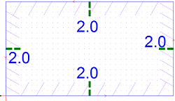
This operation is used to set a lead line in scrap region (invalid region) for closed objects, so as to avoid possible cutting errors or damage to the workpiece caused by the tool dwelling above the start point of machining for a long time.
To set a lead line, do the following:
In NcEditor, click
 and select the target object.
Note: You can check the groove direction by clicking
 .
.To open the Lead Line dialog box, do one of the following:
In the tool bar, click
 .
.In the drawing area, right click and select Set Lead Line in the pop-up menu.
In the menu bar, click Object → Set Lead Line.

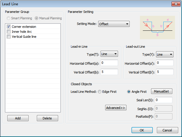
Select a lead line group :
Smart Planning: The software automatically selects a group among the preset groups for the target object.
Manual Planning: Manually select a group among the preset groups for the target object.
The preset groups include the following:
Corner extension: The extension line of corner.

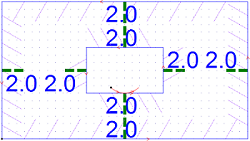
Inner hole Arc: With an arc shape, the lead line is at the center position of the longest edge.

Vertical Guide line

Select the following mode of lead line:
- Angel and length
- Line and arc
- Offset
Set the type of lead-in line and lead-out line.
Select one of the following strategies for the lead line:
Edge first: Set the lead line at the center position of the longest edge of the closed object.
Corner first: Set the lead line at the corner with the largest angle in the closed object.
Set parameter Seal Len.
If it is greater than 0, the waterjet tool will over cut at the sealing position.
If it is less than 0, the waterjet tool will not cut through at the sealing position.
To add a lead line, do one of the following:
Click OK. Lead lines will be automatically added.
Click ManualSet and select the position of lead line by your mouse.
To delete the added lead line, select the target object and do one of the following:
In the tool bar, click
 .
.In Set Lead Line dialog box, set the type of lead-in line and lead-out line to None and click OK.