Execute Other Operations
This section introduces the following auxiliary operations:
- Select picture display mode.
- Execute array machining.
- Enable CCD.
- Set the workpiece origin by CCD center.
- Set safety offset.
- Set workpiece offset compensation.
- Set workpiece size compensation.
- Set Z-axis depth compensation.
- Execute simulation.
- Set automatic layer compensation.
Select Picture Display Mode
Currently, picture display mode includes the following:
- Display live pictures captured by the camera.
- Display the shooting pictures.
After matching, whether the matching is successful or not, the picture display area in CCD Setting window displays the currently matched picture in real time.
To display live pictures captured by the camera, click the picture display area in CCD Setting window.
Execute Array Machining
To execute array machining, do the following:
Switch to Craft page:

Check Setting ON and enter the manufacturer password.
Check Array Machining to enable array machining.
Set line number and space and column number and space.
Optional: check Failed Template Exits Machining.
- Check: Only if the shooting for a workpiece fails, machining for all workpieces stops.
- Uncheck: if the shooting of a workpiece fails, machining for other workpieces continues.
Enable CCD
You can choose whether to enable CCD according to machining technics.
To enable CCD, do the following:
Switch to Craft page:

Check Setting ON and enter the manufacturer password.
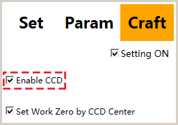
Check Enable CCD to enable CCD.
Set the Workpiece Origin by CCD Center
There are two methods to set the workpiece origin:
By tool nose
By CCD center
This ways is only suitable to shooting by two points. For other shooting methods, the workpiece origin is reset based on shooting results.
To set the workpiece origin by CCD center, do the following:
Switch to Craft page:

Check Setting ON and enter the manufacturer password.
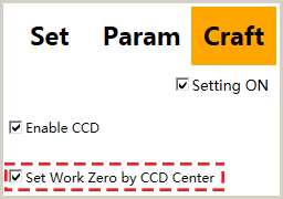
Check Set Work Zero by CCD Center to enable set the workpiece origin by CCD center.
Set Safety offset
In actual machining, the hollowed-out area on the workpiece is quite small. If the workpiece is tiled, direct machining may damage the workpiece. Thus, it is necessary to set safety offset.
The range of the safety offset and its angle is decided by the dimension of the hollowed-out area.
To set safety offset, do the following:
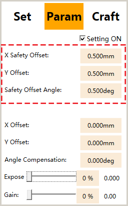
Switch to Param page and check Setting ON:

Modify the following parameters:
- X Safety Offset
- Y Safety Offset
- Safety Offset Angle
Set Workpiece Offset Compensation
In actual machining, if the machined workpiece is tilted to one side, setting workpiece offset compensation is required.
To set workpiece offset compensation, do the following:
Switch to Craft page and check Setting ON.
Click Set Part Offset Comp. Work Offset Compensation dialog box pops up:

Check Enable Offset to enable offset.
Select compensation type:
Overall compensation
It is the common compensation type.
With array machining enabled, the set workpiece offset compensation is suitable for all workpieces in the array.
Single compensation
With array machining enabled, the workpiece offset compensation of each workpiece needs to be individually set.
When lead screw of the machine results in the damage of a certain workpiece, single compensation is required.
Set related parameters for overall compensation or single compensation.
Set Workpiece Size Compensation
During machining, if the size of the machined workpiece is not the same as the ideal size, setting workpiece size compensation is required.
To set workpiece size compensation, do the following:
Switch to Craft page and check Setting ON.
Click Set Part Size Comp. Workpiece Size Compensation dialog box pops up:

Check Enable Dimension.
Select compensation type:
Overall compensation
It is the common compensation type.
With array machining enabled, the set workpiece offset compensation is suitable for all workpieces in the array.
Single compensation
With array machining enabled, the workpiece offset compensation of each workpiece needs to be individually set.
When lead screw of the machine results in the damage of a certain workpiece, single compensation is required.
Set the workpiece size.
Set related parameters for overall compensation or single compensation.
After setting, if the workpiece origin is not at the center of the workpiece, further adjust the offset compensation of X-axis and Y-axis.
Set Z-axis Depth Compensation
With array machining enabled, all workpieces are in the same horizontal plane, so one of the workpieces damaged takes a long time to machine all the workpieces from start. At this time, you can set Z-axis depth compensation for the replaced workpiece after machining.
To set Z-axis depth compensation,do the following:
Switch to Craft page and check Setting ON.
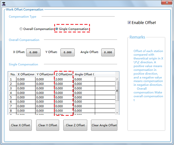
Click Set Part Offset Comp. Work Offset Compensation diaglog box pops up:

Check Enable Offset to enable offset.
Set Compensation Type as Single Compensation:
Set Z-axis offset of the corresponding station.
The station number corresponds to the shooting order.
Execute Simulation
After finishing all settings, you can execute simulation.
To execute simulation, click Simulate in CCD Setting window.
For differences between simulation and actual machining, please refer to What are the Differences between Simulation and Actual Machining?
Set Automatic Layer compensation
This operation helps to solve the problem of reusing the same tool and increase its reusing rate.
To set automatic layer compensation, do the following:
Click Operate ¡ú Auto Layer Compensation. Enable Auto Layer Comp dialog box pops up:

Check Settings ON and enter the manufacturer password to enable setting.
Check Auto Layer Comp to enable automatic layer compensation.
- Check: enable automatic layer compensation.
- Uncheck: disable automatic layer compensation.
Set the following parameters:
- Length Comp Interval
- Length Wear Increment
- Max Length Comp
Optional: Click Clear Counter to clear values of the column Finished Times.
Optional: Click Clear All to clear values of all columns, except the column Max Length Comp.
After setting, click Start to start machining:
The system executes length compensation based on Length Wear Increment of all tool.
After completing machining once, the values of Finished Times automatically adds 1 and the system judges whether Length Comp Interval has reached.
Reach: the system accumulates a Length Wear Increment to the value of Real-time Length Comp and judges whether the value of Real-time Length Comp exceeds the value of Max Length Comp.
- Exceed: an alarm The compensation values of automatic layer compensation exceeds the upper limit. Cannot continue machining! pops up and machining with current tool stops.
- Not exceeded: machining continues.
Not reached: the value of Real-time Length Comp keeps unchanged and machining continues until the value of Finished Times is equal to the value of Length Comp Interval.