Frequently Asked Questions(FAQ)
This section contains answers to common questions in NcStudio V12 CCD Control System.
For additional questions, contact our technical sales engineers.
May Errors Exist in the CCD? If Errors Exit, Why It Happens?
Errors may exists in the CCD.
The image algorithm takes pixel as its unit and its accuracy is ±1 pixel.
Example
If the magnification is 200, that is, 200 pixels corresponds to 1 mm, then the error range in the CCD is ±0.005.
How Much Error Does the Finished Workpiece Exist in the CCD?
The error value at the shooting point is ±1 pixel and the error value of the finished workpeice is determined by specific workpieces.
Example
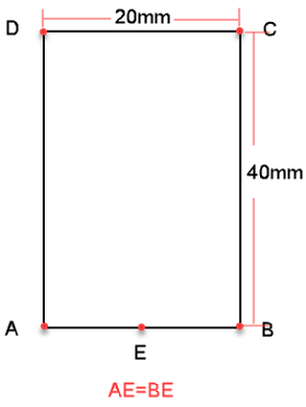
If the following workpiece is machined:

Then: the maximum error value in machining point C is CE/BE*1 pixel, which is about 2.2 pixels.
If the magnification is 200,
- The maximum error value of point C and point D is 0.011mm.
- The maximum error value of point A and point B is 0.005mm.
If Errors Exist in the Finished Workpiece, What to Do?
If errors exist, firstly confirm whether the error value is within the reasonable error range:
- If the error value is within the reasonable error range, do nothing.
- If the error value is not within the reasonable error range, do the following to troubleshoot the issue.
Troubleshooting
Check the magnification.
See Measure Magnification for details.
Check the installation of the camera or lens:
Tap the camera to see if the imaging is shaking.
Manually test the installation.
See How to test the installation of the camera or lens for details.
Check the setting of shooting points.
See Shoot for details.
Check the shoot delay time to see if it is too short.
If the shoot delay time is too short, shooting will be calculated without the machine's stop. The image obtained at this time may not be the image obtained after moving to the shooting point. Thus, the calculated position may exist errors.
For judging the setting of the shoot delay time, please refer to Set the Camera for details.
Check the template.
Incorrect template setting leads to errors in images matching.
It is recommended to observe for a while after setting the template to ensure stable machining.
How to Test the Installation of the Camera or Lens?
To test the installation, do the following:
Manually move X-axis towards negative direction.
Click To Shoot and save the image.
Manually move X-axis towards positive direction.
Click To Shoot and save the image.
Move Y-axis and repeat the above steps.
Observe the saved images in image viewer to see if the images are different.
If the images are different, it shows the camera is not fixed or the machine's accuracy is not enough.
What is the Impact of Incorrect Position of Shooting Points in Shooting by Two Points?
Incorrect position of shooting points results in errors in the machined workpiece.
In general, the two shooting points in shooting by two points should be horizontal or vertical and the coordinates of the two points should be symmetrical.
What are the Differences between Simulation and Actual Machining?
The main differences are as follows:
- Tool nose is used in actual machining; while view center of the camera is used to simulate along tool path in simulation.
- Z-axis moves along tool path in actual machining; while Z-axis moves at the focal height in simulation.
Before actual machining, it is recommended to execute simulation to check all settings.
What Are the Requirements for the Selected Feature Points in Measuring Magnification?
The feature point must be unique in the camera view.
Example
In the figure below, the rectangle in the left is not unique in the view, so it cannot be set as a feature point to measure magnification; the cross in the right is unique in the view, so it can be set as a feature point to measure magnification.
