Set CCD and the Workpiece
To set CCD and the workpiece, do the following:
Set Image Matching Mode
With a few exceptions, most feature points are the same.
For shooting points with the same features, you only need to set a template; for shooting points with different features, you need to set templates for each shooting point.
To set image matching mode for feature points, do the following:
Switch to Param window and check Operation parameters.
Set parameter 26003 CCD Image Match Mode:
- If the feature points are exactly the same, set the parameter to O.
- If the feature points are different, set the parameter to 1.
Shoot
To shoot, do one of the following:
These methods differ in the number of shooting points:
Comparison between shoot by two points and other operations is as follows:
Differences Shoot by two points Shoot by single/three/four point(s) Used coordinate Workpiece coordinate Machine coordinate Shooting position Input manually. Directly move to the corresponding position and set. When to set coordinate system Set before machining. Reset based on the actual position after shooting. Difference between shoot by three points and Shoot by four points:
The later is actually an upgraded operation of the former. If shooting a point fails in shooting by three points, shooting by four points is required.
Shoot by Single Point
When programming, you need to set the circle center as the workpiece origin. After shooting, the system will set the found center as the workpiece origin.
This operation is suitable to process circles.
To shoot by single point, do the following:
Switch to Param page and set the parameter CCD Shoot mode to 1.
Move to the circle center and click Shoot to record the position of the shooting point.
After setting, click Template Edit. Outline Positioning dialog box pops up. For details, please refer to Edit a Template.
Shoot by Two Points
With this shooting method, the positions of the shoot points are the theoretical position on the drawing.
To shoot by two points, do the following:
Set the workpiece origin and the first shooting point:
It is recommended to do the following:
Switch to Craft page and check Setting ON and Set Work Zero by CCD Center.
Move X-axis and Y-axis to the position of the first shooting point, and click Clear → X and Y.
Switch to Set page and click Pick Current under Mark 1.
At this time, the position of the first shooting point is the workpiece origin.
Switch to Param page and set the parameter CCD Shoot Mode to 2.
Set the second shooting point under Mark 2.
It is recommended to manually input the position of the second shoot point, according to the distance between the two shooting points.
Example
In the figure below, the two shooting points are horizontal in X-axis direction with 40mm distance and the first shooting point is set as workpiece origin:
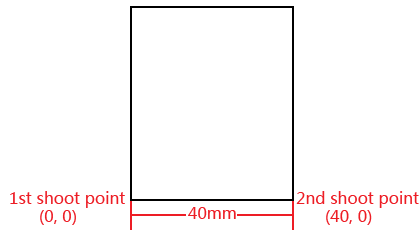
Thus, the position of the second point is (X40, Y0).
After setting, click Template Edit. Outline Positioning dialog box pops up. For details, please refer to Edit a Template.
Shoot by Three Points
With this shooting method, the three points must form a right triangle. And when programming, you need to set the center point of the hypotenuse as the workpiece origin.
To shoot by three points, do the following:
Switch to Param page and set the parameter CCD Shoot Mode to 3.
Move X-axis and Y-axis to the position of the first shooting point and click Pick Current under Mark 1.
Move X and Y axes to the position of the second shooting point and click Pick Current under Mark 2.
Move X and Y axes to the position of the third shooting point and click Pick Current under Mark 3.
After setting, click Template Edit. Outline Positioning dialog box pops up. For details, please refer to Edit a Template.
Shoot by Four Points
This method is similar to shooting by three points. If shooting a point fails in shooting by three points, shooting by four points is required.
To shoot by four points, do the following:
Switch to Param page and set the parameter CCD Shoot Mode to 4.
Move X-axis and Y-axis to the position of the first shooting point and click Pick Current under Mark 1.
Move X-axis and Y-axis to the position of the second shooting point and click Pick Current under Mark 2.
Move X-axis and Y-axis to the position of the third shooting point and click Pick Current under Mark 3.
Move X-axis and Y-axis to the position of the fourth shooting point and click Pick Current under Mark 4.
After setting, click Template Edit. Outline Positioning dialog box pops up. For details, please refer to Edit a Template.
Edit a Template
The purpose of editing a template is to extract features of shooting points. Thus, it is convenient to find the position of the feature points in the picture according to the extracted features.
When editing a template, please ensure:
- The number of extracted feature points is enough.
- The workpiece is not tilted, because it is not allowed to pick the feature points while the feature points are tilted.
To edit a template, do the following:
Click Edit. The Outline Positioning dialog box pops up.
Switch to Set Template page and click Reset Template.
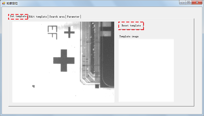
Drag the rectangle to the position of the feature point:
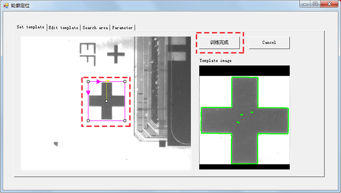
The size of the rectangle needs to be equal to the size of the feature point.
After it is done, click Finish.
Switch to Edit Template page to process the extracted features:

Min Contrast and Max Contrast
: Used to set the contrast of the feature points.
: In general, the range of the minimum contrast is [20, 80] and the range of the maximum contrast is [60, 120].
: If the picture is blurry and the feature points are not obvious, you can lower these two values.Edge Min Length
: The minimum pixel of the extracted feature point's edge.
: In general, it is set to 10.Erase Dimension
: The dimension of eraser that used to erase unnecessary parts.After it is done, click Apply.
Switch to Search Area page to set search area for the feature points.
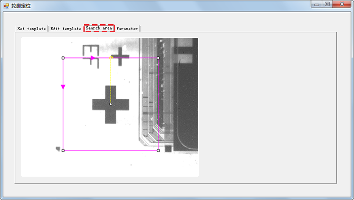
In general, the feature point is near the center of the picture. Thus, it is recommended to select a smaller range.
Switch to Param page and set parameters for outline positioning:
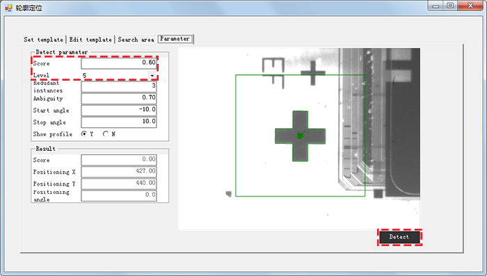
Set the parameters Score and Level according to the picture quality. If the picture quality is good, these two parameters can be set higher.
Remember too small values result in wrong positioning and too big values result in positioning missing.
In general, the range of the parameter Score is [0.3, 0.7] and the range of the parameter Level is [4, 6].
After it is done, click Detect to detect whether shooting is successful.
After the setting is completed, it is necessary to repeatedly observe in case of mistakes.