Operating Interface
The operating interface of NcStudio V12 CCD Control System is as follows:
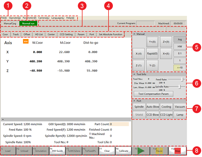
- Menu bar
- Status bar
- Machine control bar
- Function windows
- Manual control area
- Tool information area
- Port control area
- Operating buttons
Function windows
Function windows include the following:
- Coor window
- Track window
- Offset window
- HD List window
- Center window
- CCD Setting window
- Param window
- Port window
- Set Absolute Function window
Coor Window
This window shows machine coordinate system and workpiece coordinate system:
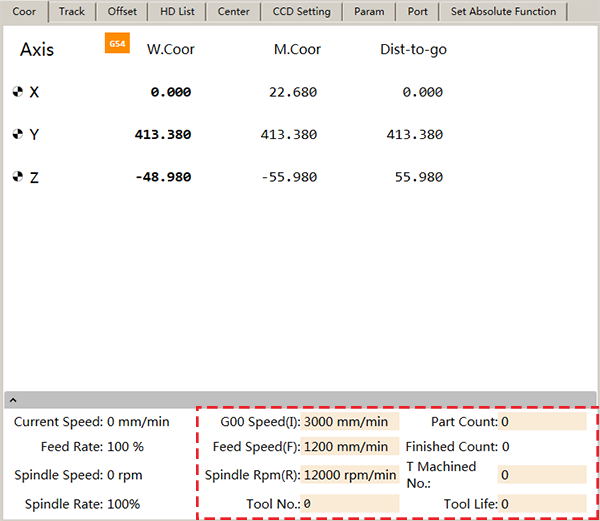
You can click the input boxes in yellow to directly edit the value of related parameters.
After axes have returned to the machine origin, the sign  will appear before related axes.
Track Window
This window shows the machining track of tool in real time:

- Toolbar
- Track display area
- Right-click menu
- Machining file area
Offset Window
In this window, you can set workpiece offset and public offset, which is good for programming and shortening axis moving distance:
- Workpiece offset: it shows the distance of the workpiece origin relative to the machine origin.
- Public offset (external offset): it records temporary adjustment value of the workpiece origin and it can only be modified manually.
The relationship among workpiece offset, tool offset and public offset is as follows:
Workpiece Coordinate = Machine Coordinate — Workpiece Offset — Public Offset — Tool Offset
With Automatic Layer Compensation enabled, the relationship turns to:
Workpiece Coordinate = Machine Coordinate — Workpiece Offset — Public Offset — Tool Offset — Real-time Length Compensation
Among them, Tool Offset can be set by switching to Param window and modifying Tool parameters.
To set workpiece offset and public offset, do the following:
To set workpiece offset, do the following:
Click the workpiece coordinate system to select a workpiece coordinate system:
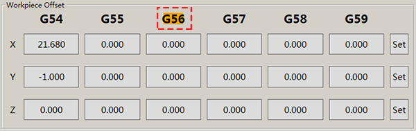
The selected coordinate system turns to orange.
Click the input box of related axis and set a value.
Click Set to set the machine coordinates of the current point to the offset.
To set public offset, do the following:
To set public offset for X-axis/Y-axis, click the input box of related axis and set a value:

To set public offset for Z-axis, do one of the following:
Click the input box of Z-axis and set a value.
Click the input box of Scale, set a value and do one of the following:
- Click Deepen. The workpiece origin of Z-axis moves down the corresponding distance.
- Click Lift. The workpiece origin of Z-axis moves up the corresponding distance.
HD List Window
This window includes the following interfaces:
Local interface
It shows the list of local program files under the root directory D:/NcFiles.
USB interface
It shows the list of program files from removable flash disks both under the root directory and subdirectory folders.
Wizard interface
You can generate program files from the following program wizards:
- Cir. Contour
- Cir. Pocket
- Rect.Contour
- Rect.Pocket
In conclusion, in this window, you can access various program files, stored in the system and in removable flash disks and generated from wizard.
Center Window
In this window, you can define the workpiece origin for regular rectangular workpiece through finding the center point by two points on the workpiece:
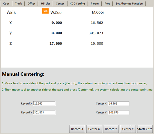
To do centering, do the following (take centering X-axis as an example):
Turn off the spindle to avoid danger from too fast spindle speed.
Click StartCenter.
Move the tool to one side of the workpiece and press Record X. The system records the machine coordinates of current point.
Move the tool to the other side of the workpiece and press Center X. The system does the following:
- Record the machine coordinates of current point.
- Calculate the center point based on coordinates of current point and previous point.
Note: When one axis is centered, the other axis should keep still.
CCD Setting Window
In this window, you can execute operations of CCD setting:

To Shoot
CCD moves to the related shooting position.
To Focal Height
Spindle moves to the clearest position of the picture.
Simulate
Spindle moves to the clearest position of the picture and then moves along tool path.
No actual machining occurs.
Basic Setting
Click this button, CCD Basic Setting interface pops up:
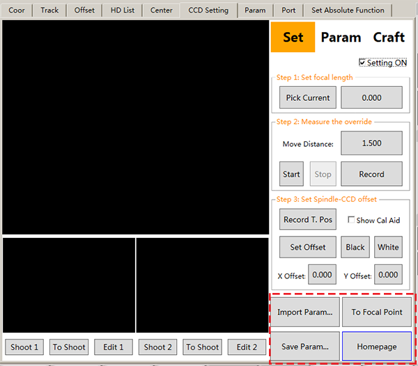
- Save Param: save CCD related parameters.
- Import Param: import parameters saved by Save Param operation.
- To Focal Point: move the camera to the focal height.
- Homepage: jump to CCD Setting window.
This function window is quite important in this manual. This section only focuses CCD function. For CCD operations, please refer to CCD Operations.
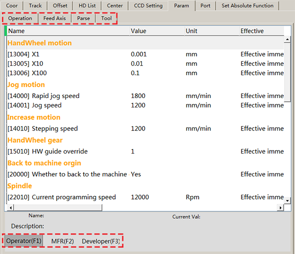
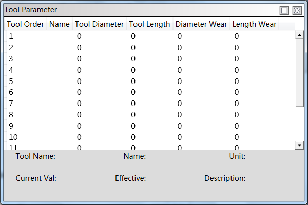
Param Window
This window shows all parameters in NcStudio V12 CCD Control System:
You can check and modify the values of parameters by:
Function
Parameters are divided into Operation, Feed Axis, Parse and Tool.
In running state, only parameters of tools except the current tool can be modified.
Permission
Parameters are divided into Operator, MFR (manufacturer) and Developer.
For MFR and developer parameters, password is required.
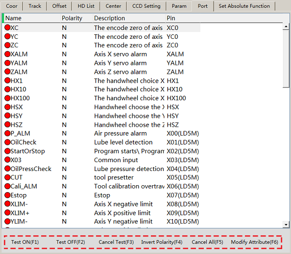
Port Window
This window shows port information:
Set Absolute Function Window
In this window, you can set the machine origin, also known as datum:
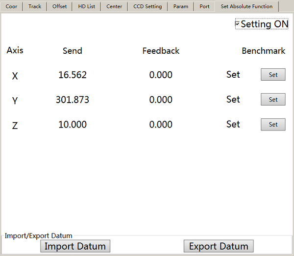
This operation is required only commissioning for the machine tool is required.
To set datum, do one of the following:
- Click Set to set current coordinate as datum.
- If you have replaced the software, click Import Datum to import previously set datum parameters.
After setting, click Export Datum to export the set datum for later use.
Operating Buttons
You can click corresponding buttons or shortcut keys (F1~F11) to realize corresponding operation:
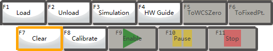
Among them, Clear (F7) is used to clear the pubic offset.
Click it to select the corresponding axis to do clearing:
![]()
Port Control Area
In this area, you can detect the communication of software and hardware.

Click corresponding button. The port turns to green and the related valve is on.
Lights ON of the port in the terminal board shows good communication.
Tool Information Area
In this area, you can check tool information:
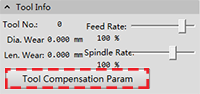
Click Tool Compensation Param to set tool compensation parameters:
Manual Control Area
In this area, you can control axis movement and select feed mode:
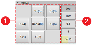
Axis direction buttons: used to move each axis towards positive or negative direction:
Only click an axis button. The axis moves at jogging speed.
Click an axis button after clicking Rapid. The axis moves at rapid jogging speed.
Mode buttons: used to select feed mode:
Jog mode
Press an axis direction button and Jog. The machine tool keeps running until you release the button.
HW mode
The machine tool is controlled by handwheel.
Stepping mode
Click an axis direction button and 0.1, 1 or the left yellow area on button >>10. The machine moves 0.1mm, 1mm or a customized step size separately.
Click the right grey area on button >>10, Stepsize dialog box pops up and you can customize the step size.
The customized step size should not be too large to avoid damage from misoperation. And its default value is 10mm(inch).
Note: Please do not click frequently, for the system needs a certain time to execute the command.